
Objectives
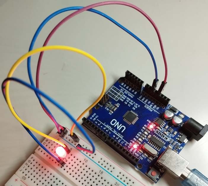
In this chapter, we will understand the basics of a circuit and demonstrate building one using a breadboard.
Prerequisites
Setup
Arduino Uno Board
Jumper Wires
LED (2 legs)
Breadboard (also known as a Solderless Board)
About Circuits
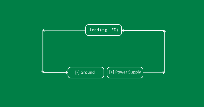
A closed circuit is a complete, uninterrupted path allowing electric current to flow. Some key components of a closed circuit include:
Power supply: Provides the energy for the current flow such as a battery,
Load: A material that uses energy such as a light bulb or LED, and
Conductor: A material that allows electricity to flow such as wire.
The flow of electricity starts from a supply (indicated with a "+" symbol), then travels through a conductor, then gets used by a load if one exists, and finally exits at the ground (indicated with a "-" symbol).
Building a Circuit
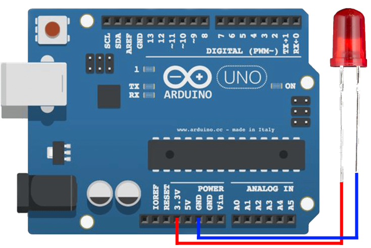
We can demonstrate a closed circuit using an LED and jumper wires without a breadboard:
Grab a jumper wire and plug one end of the pin into the "3.3v" (Power Supply) in the Arduino Board. Attach the other end of the jumper wire to the longer leg (Anode) of an LED. (Warning: Don't attempt the "5v" unless you're sure that your LED supports a 5 volt rating, otherwise it'll go bust)
Grab another jumper wire and plug one end of the pin into one of the GND (Ground) in the Arduino board. Attach the other end of the jumper wire to the shorter leg (Cathode) of the LED.
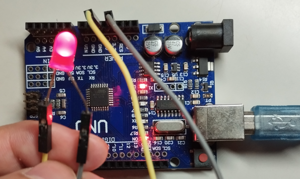
Upon following the above-said steps, you should notice the LED lighting up. The "3.3v" and "5v" voltage regulators in the Arduino Uno board are our power supply. Other pin holes (but not all) in the Arduino board can also be used as our power supply but have to be explicitly told through the source code (We'll get more to that later in the future chapters).
Moving on to the Breadboard...
A breadboard is a board that has rows and columns of pin holes. We can attach more conductors (e.g. jumper wires) and loads (e.g. LEDs, Buttons, Sensors, etc.). Most of the time, as the project gets more sophisticated, a breadboard is a necessity.
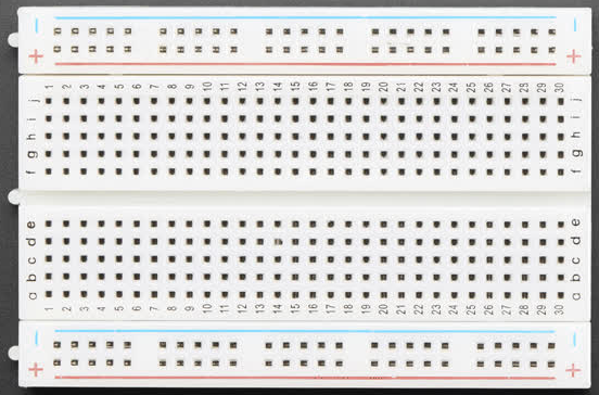
Under a breadboard are metal strips that serve as a conductor of energy. It is important to know how these metal strips are arranged in the breadboard so that we can successfully create a closed circuit:
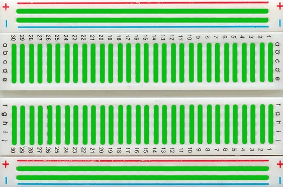
From the above example, the green highlights are the metal strips under the breadboard.
Lighting up an LED on a Breadboard
Alright, we're ready to create a closed circuit, and this time we will light an LED that is pinned to a breadboard:
Grab a jumper wire and pin one end to Arduino Uno's "3.3v" (Power supply). Pin the other end to any of the hole in the "+" column of the breadboard.
Grab a jumper wire and pin one end to any of the holes in the "+" column. Pin the other end to the "a5" coordinate of the breadboard.
Grab an LED and pin the longer leg (Anode) to the "c5" coordinate of the breadboard. Pin the shorter leg (Cathode) to the "c6" coordinate of the breadboard.
Grab a jumper wire and pin one end to the "d6" coordinate of the breadboard. Pin the other end to any of the hole in the "-" column of the breadboard.
Grab a jumper wire and pin one end to any of the hole in the "-" column of the breadboard. Pin the other end to the GND (Ground) in the Arduino board.
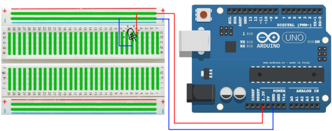
Following the steps above, you should notice the LED light up. As long as we are mindful of the arrangement of the metal strips under the breadboard, we can arrange a closed circuit in many ways.