
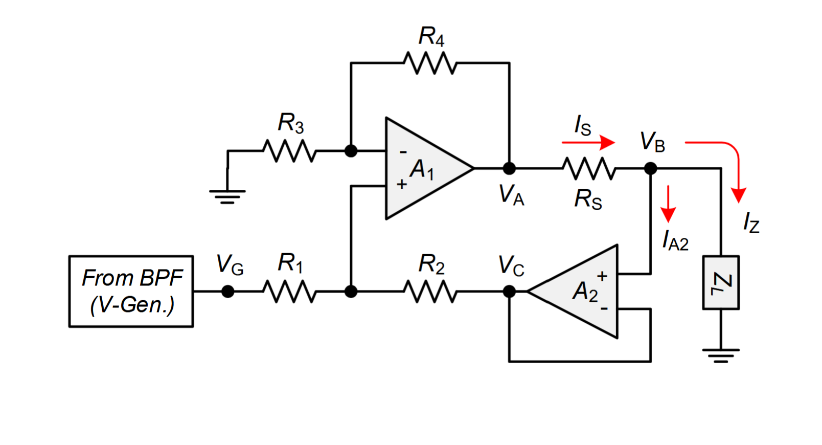
 Figure 1. Buffered-feedback Howland current source used in the bio-impedance spectrometer. Reproduced from Santoso et al. [10].
A wideband Howland current source is about
impedances, not just resistance
A Howland current source is usually introduced as a circuit whose accuracy depends on carefully matched resistor ratios.
That is true at DC.
At higher frequencies, however, it is no longer enough.
The circuit does not really operate on resistor ratios. It operates on impedance ratios.
This distinction becomes important when we want a Howland current source to maintain high output impedance, predictable transconductance and good dynamic behaviour over a wide frequency range.
The DC condition is only the beginning
The familiar balance condition of a Howland current source is normally written using resistors.
For a wideband analysis, the more general condition is:
Z₁(s) / Z₂(s) = Z₃(s) / Z₄(s)
At DC, where s=0, this reduces to the usual resistor-ratio condition.
But as frequency increases, each branch contains more than its nominal resistance.
Input capacitance of the op-amp, PCB capacitance, resistor parasitics and other stray capacitances become part of the circuit.
It is therefore entirely possible to have:
R₁/R₂ = R₃/R₄
while at some frequency:
Z₁(jω)/Z₂(jω) ≠ Z₃(jω)/Z₄(jω)
The Howland bridge is then perfectly balanced at DC but progressively unbalanced for AC.
The result can be a reduction in output impedance, a change in transconductance, additional phase shift, peaking, ringing or even oscillation.
Wideband Improved Howland Current Sources with lead-lag compensation have been analysed specifically in this context [3].
Why matching RC time constants works
Consider two branches consisting of a resistor in parallel with a capacitor:
Z₁(s) = R₁ / (1 + sR₁C₁)
Z₂(s) = R₂ / (1 + sR₂C₂)
Their ratio is:
Z₂(s)/Z₁(s) = (R₂/R₁) · (1 + sR₁C₁)/(1 + sR₂C₂)
If the time constants are equal:
R₁C₁ = R₂C₂
then the frequency-dependent terms cancel and:
Z₂(s)/Z₁(s) = R₂/R₁
The impedance ratio remains constant with frequency, as long as this first-order R∥C model remains a reasonable approximation.
This is the same basic principle used in compensated voltage dividers and oscilloscope probes: a parasitic capacitance in one branch can be compensated by an appropriate capacitance in the other branch so that the pole and zero coincide [1], [2].
Applying this to the Howland bridge
For the Howland source, the fundamental requirement is that the two impedance ratios remain equal:
Z₁(s)/Z₂(s) = Z₃(s)/Z₄(s)
There are actually two related goals here, and they should not be confused.
The first goal is simply to maintain bridge balance.
The second, stronger goal is to make each divider preserve its original resistive ratio over frequency.
For branches that can be approximated as R∥C, a convenient sufficient condition for the second goal is:
R₁C₁ = R₂C₂
and
R₃C₃ = R₄C₄
In other words, the important design rule is:
match impedances, not only resistors.
RC matching is not the same as loop stability
There is an important limitation.
Correcting the impedance ratios does not automatically guarantee that the complete current source is stable.
The full loop gain still depends on the op-amp open-loop gain and phase, its internal poles, the load, output capacitance, PCB parasitics and other high-frequency effects.
So the correct order of thinking is:
first, eliminate unintended frequency dependence in the passive impedance ratios;
then analyse the complete feedback loop;
RC matching can remove an important source of gain and phase error, and in some cases it can transform a circuit that rings or oscillates into one that behaves correctly.
But it is not a universal stability equation.
Sources and further reading
[1] Texas Instruments, Stability Analysis of Voltage-Feedback Op Amps Including Compensation Techniques (SLOA020).
https://www.ti.com/lit/pdf/sloa020
[2] Linear Technology / Analog Devices, AN148 — High Speed Amplifier Techniques
https://www.analog.com/media/en/technical-documentation/application-notes/an148fa.pdf
[3] Tucker, Fox, Sadleir, Biocompatible, High Precision, Wideband, Improved Howland Current Source With Lead-Lag Compensation.
https://ieeexplore.ieee.org/document/6221965/
[8] Rafiei-Naeini, McCann, Low-noise current excitation sub-system for medical EIT.
https://www.pure.ed.ac.uk/ws/files/94036990/Low_noise_current_excitation_EIT.pdf
[9] Bouchaala, Kanoun, Derbel, Minimization of stray capacitances in Howland current source.
https://www.imeko.info/publications/tc13-2014/IMEKO-TC13-2014-15.pdf
[10] Didik R. Santoso, Bella Pitaloka, Chomsin S. Widodo, Unggul P. Juswono, Low-Cost, Compact, and Rapid Bio-Impedance Spectrometer with Real-Time Bode and Nyquist Plots, Applied Sciences, 2020, 10(3), 878.
https://www.researchgate.net/publication/338872742_Low-Cost_Compact_and_Rapid_Bio-Impedance_Spectrometer_with_Real-Time_Bode_and_Nyquist_Plots
[11] Ignacio Vazquez Lam, Analysis of Improved Howland Current Pump Configurations, Texas Instruments, Application Note SBOA437A, October 2020, revised February 2023.
https://www.ti.com/lit/an/sboa437a/sboa437a.pdf