

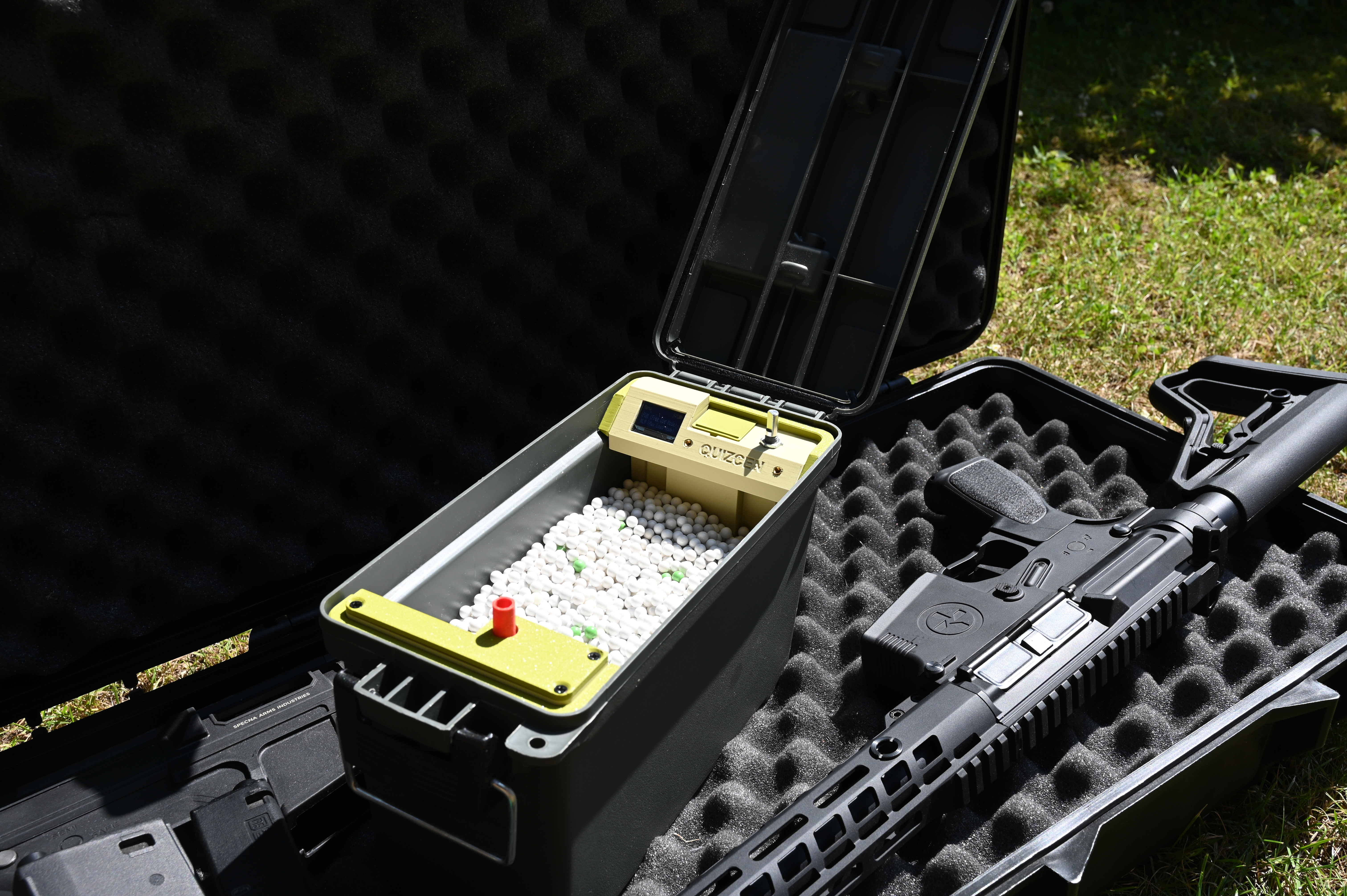
Thank you for your interest in the EAS MAX. This is a complete guide on how to build everything. The first video here explains how you should source components, how to buy the kits, and a quick walkthought of the entire setup.
VIDEO IN DEVELOPMENT!
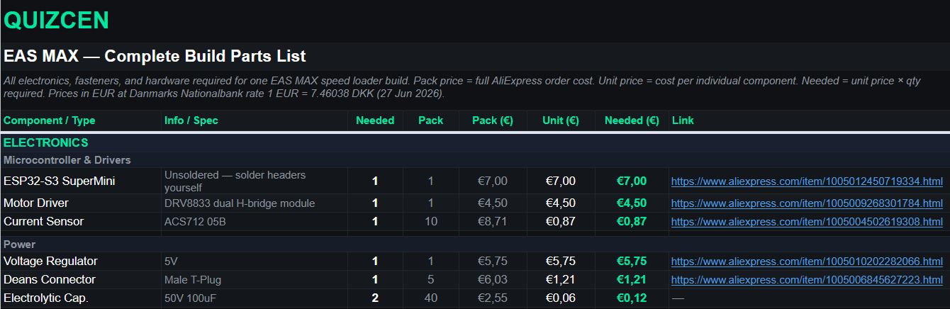
Complet part list For EAS MAX V1.0: LINK TO SPREADSHEET
 Print settings.
PETG — Recommended for the entire build
PETG is the go-to filament for the EAS MAX. It handles heat, humidity, and the mechanical stress of repeated loading cycles well. If you only want to use one filament for the whole build, use PETG throughout.
Tested and confirmed working filaments:
Anycubic PETG
Prusament PETG
Bambu Lab PETG HF
These are the filaments all development parts were printed in. Any quality PETG from a reputable brand should work fine.
PLA — Acceptable for non-critical parts only
PLA can be used for the large outer box, lids, and other structural panels that do not come under mechanical stress or heat. Do not use PLA for any moving or load-bearing components.
Do NOT print in PLA: EV01, EV02, Nozzle, Driver wheel or Any part that contacts BBs or experiences movement
NYLON — Required for heavy-use
The driver wheel is the most wear-critical part in the system. PETG will work for most builds, but it will wear down over time depending on your filament brand, print settings, and the type of magazines you load.
When to switch to nylon:
If you primarily load PTS1 240-round magazines or other high-capacity mags, print the driver wheel in plain nylon — not fiber-filled. Fiber-filled nylon is too brittle for this application.
If you load standard midcap magazines, PETG should hold up well for a long time.
How to tell when the driver wheel needs replacing:
Inspect the teeth on the wheel. When they start to look bent, shiny, or rounded off, it is time to print a replacement. Catching this early prevents feeding issues.
For maximum strength with nylon, anneal the part after printing. This relieves internal stress and significantly increases toughness. Look up annealing guides specific to your nylon brand for temperature and timing — it is a straightforward process and well worth doing.
SLICER SETTINGS
Nozzle size: 0.4mm
Layer height: 0.2mm
Do not change either of these. All parts have been designed and optimised specifically for a 0.4mm nozzle at 0.2mm layer height. Using a larger nozzle or different layer height will affect tolerances, fit, and part strength.
All parts are already oriented correctly in the STL files. Do not rotate them — the orientations have been chosen to maximise strength and minimise the need for supports.
Supports
Only one part requires supports:
EV01 — add support to the long channel section where the BBs travel. Support this area only. Do not add supports to the rest of the part
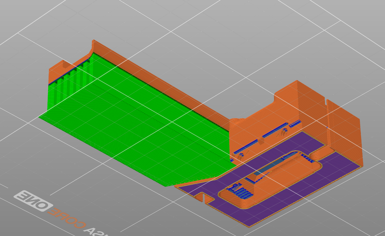 All other parts have been designed to print without supports. Do not add supports elsewhere — they are not needed and will create extra cleanup work.
Print speed
Print all driver components slowly. This is the most important setting adjustment you can make. Slower speeds produce better layer adhesion, tighter tolerances, and longer-lasting parts on the components that matter most.
For everything else, standard speed settings for your PETG profile work fine. There is no need to slow down the entire print.
All development parts were printed using standard 0.2mm PETG profiles — generic profiles in Bambu Studio and PrusaSlicer both work well without modification.
All parts in this project have been printed and field-tested on: Bambu Lab P2S, H2C, X2D, Prusa Core One
Any well-calibrated printer capable of printing PETG reliably should produce good results.
QUICK REFERENCE
Nozzle: 0.4mm (do not change)
Layer height: 0.2mm (do not change)
Filament: PETG for most parts
Nylon (plain) for driver wheel if loading high-cap mags
Supports: EV01 only — BB channel section only
Orientation: Pre-set in STL files — do not rotate
Speed: Slow for driver components, standard for everything else
Sanding: Minimal — most parts fit straight off the printer
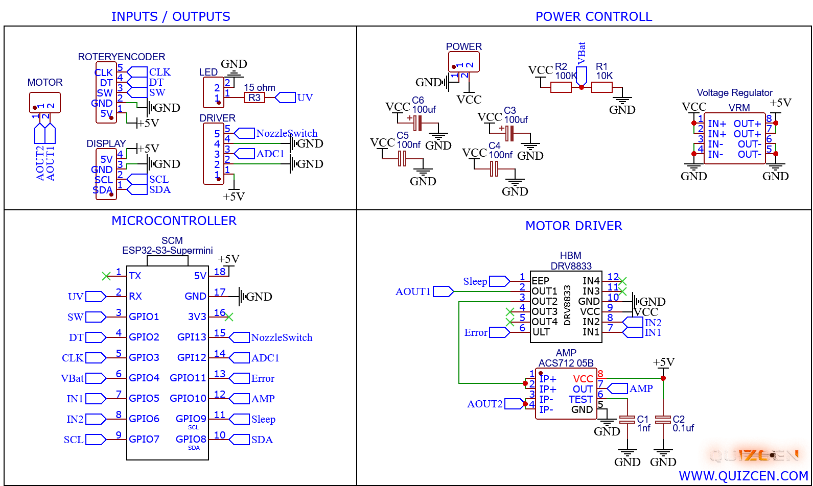
Wirering schematic.
Use this for refrence if you build it on a prototype board. In this case remember that some components are SMD.
Below you can see how everything is wired up. If you are just building one you can make the pcb yourselves on a prototype pcb. For the current sensor use a standalone module with components soldered to that. The SMD Capasitors is not stricly needed but help to keep voltage steady.
 PCB
PCB
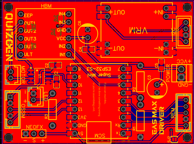
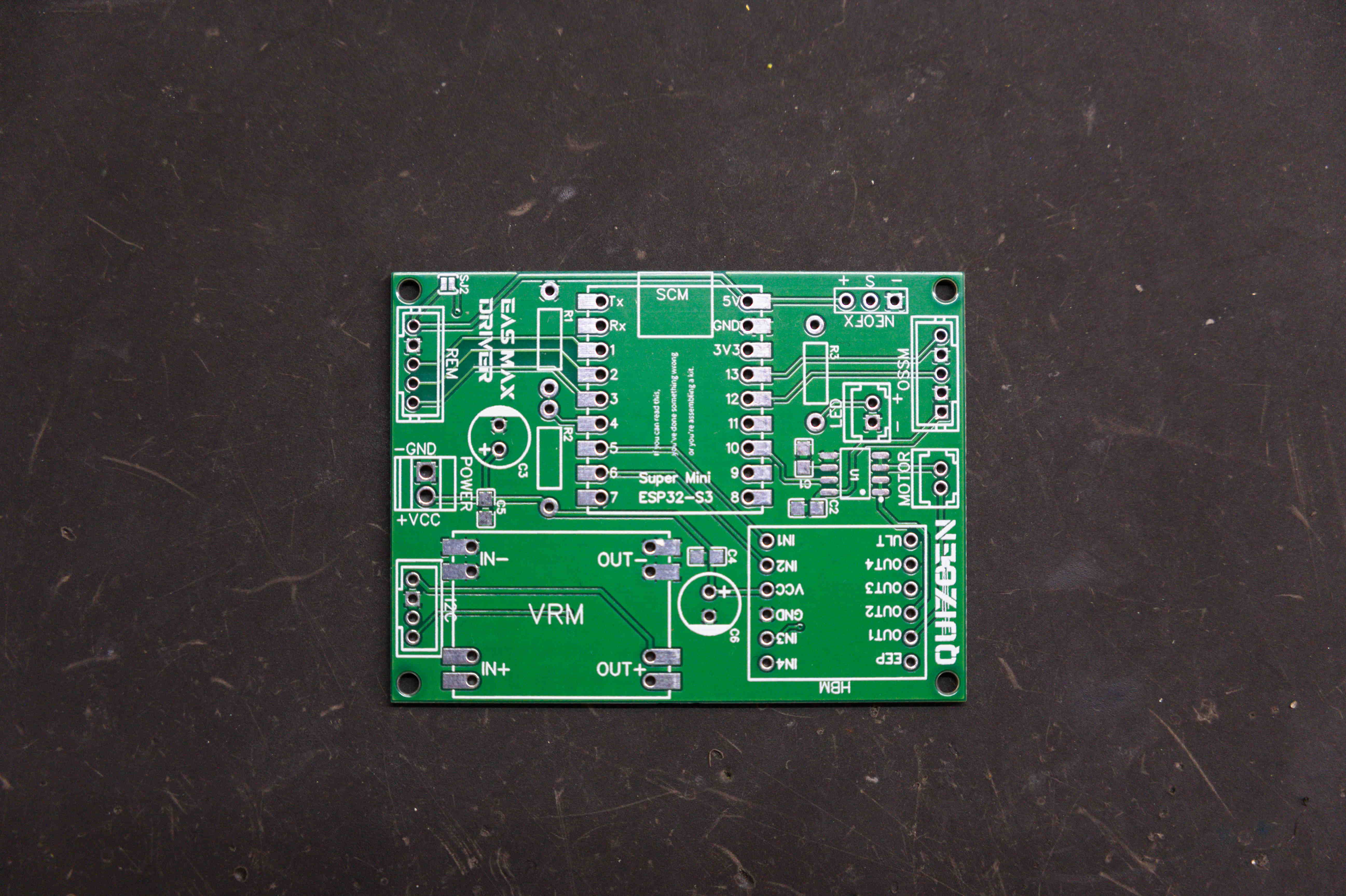
The EAS MAX runs on a custom-designed PCB built around the ESP32-S3 SuperMini and DRV8833 motor driver. You have two options for getting the board.
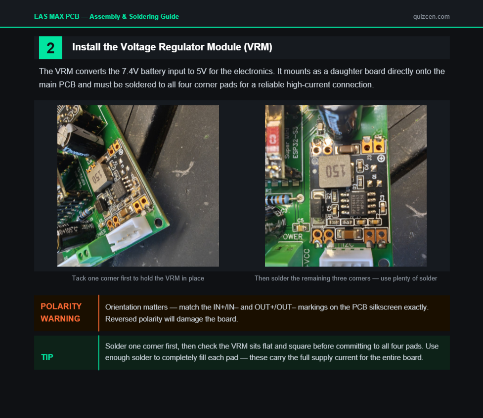 You can download the PCB assembly guide here
Option 1 — Make it yourself (Gerber files)
If you want to have the PCB manufactured yourself, the Gerber files are available at:
quizcen.com/products/eas-max-gerber-filesDownload the files, upload them to your preferred PCB manufacturer (JLCPCB, PCBWay, etc.), order your boards, source the components from the parts list, and solder everything yourself. This is the most cost-effective route if you are comfortable with PCB ordering and soldering.
Option 2 — Buy the premade PCB kit
If you would rather skip the manufacturing step and support the project, the PCB is available in several kit versions at:
quizcen.com/products/eas-max-pcb-kitsBarebone PCB, SMD pre-soldered, or full component kit — choose how much you want to solder yourself.
A note on why everything is split into separate products
I have put a serious amount of hours into designing, optimising, and field-testing the EAS MAX — from the PCB layout to every printed part. Splitting things into separate products is not just about the shop structure. It means I can update individual components without touching everything else, and more importantly, it lets you as the builder pick exactly what you need and skip what you don't. If you want to source all the electronics yourself, you can. The goal is flexibility — you should only spend money on the parts that actually help you.
EAS MAX Assembly video
Upload the Firmware
You can get the firmware here: Link to firmware
The same link also includes a flashing guide you can follow to flash the custom firmware onto your EAS MAX.
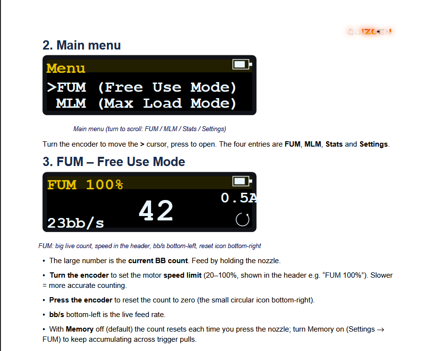
Firmware Documentation
If you own the custom firmware, a PDF guide is included that walks through all the features, how to apply settings, and calibration. Get the EAS MAX FIRMWARE
 Need help along the way?
Watch the full assembly walkthrough on YouTube for a step-by-step visual guide, or hop into the Discord community if you get stuck — that's the fastest way to reach me directly and see how other builders tackled the same steps.
Ready for more? Browse the full EAS MAX lineup and pick up any parts or kits you're missing at quizcen.com.
Thanks for building with Quizcen.