

Objectives
This chapter guides how to display text using a Liquid Crystal Display (LCD) module, with the inclusion of a potentiometer component to adjust the display contrast.
Prerequisites
Setup
Jumper Wires
Breadboard
Arduino Uno board
LCD (16 columns x 2 rows)
Potentiometer (10k ohms)
Installing the LCD
The topic of LCD is extensive, however, our discussion will be centered on their integration with Arduino. LCDs are primarily designed for text display, they become particularly versatile when combined with other modules, for instance, displaying sensor data such as temperature, humidity, light intensity, or distance. They can also serve to provide status updates or facilitate user interaction. While there's much more to explore where it can be used, this should give a basic understanding.
Let's proceed to discuss the integration of an LCD into an Arduino project. Please observe that the LCD module has 16 pins; we need to connect many of them to the Arduino board. Given the multitude of pins in the LCD and the limited number of pinholes on the Arduino Uno board, utilizing a breadboard would be ideal for this demonstration.
We need to let power flow to the breadboard. Grab a jumper wire and pin one end to Arduino Uno's "5v" pinhole. Pin the other end to any of the pinhole in the "+" column of the breadboard.
Next, we have to setup a ground reference in the breadboard. Grab a jumper wire and pin one end to Arduino Uno's "Gnd" pinhole. Pin the other end to any of the pinhole in the "-" column of the breadboard.
Now, snap the LCD's pinholes in the breadboard. Put the first pinhole of the LCD in the "a1" coordinate of the breadboard. Since we cannot separate pins in the LCD, this would mean that the next 15 pins would occupy the coordinates "a2", "a3", "a4", and up to "a16" of the breadboard.
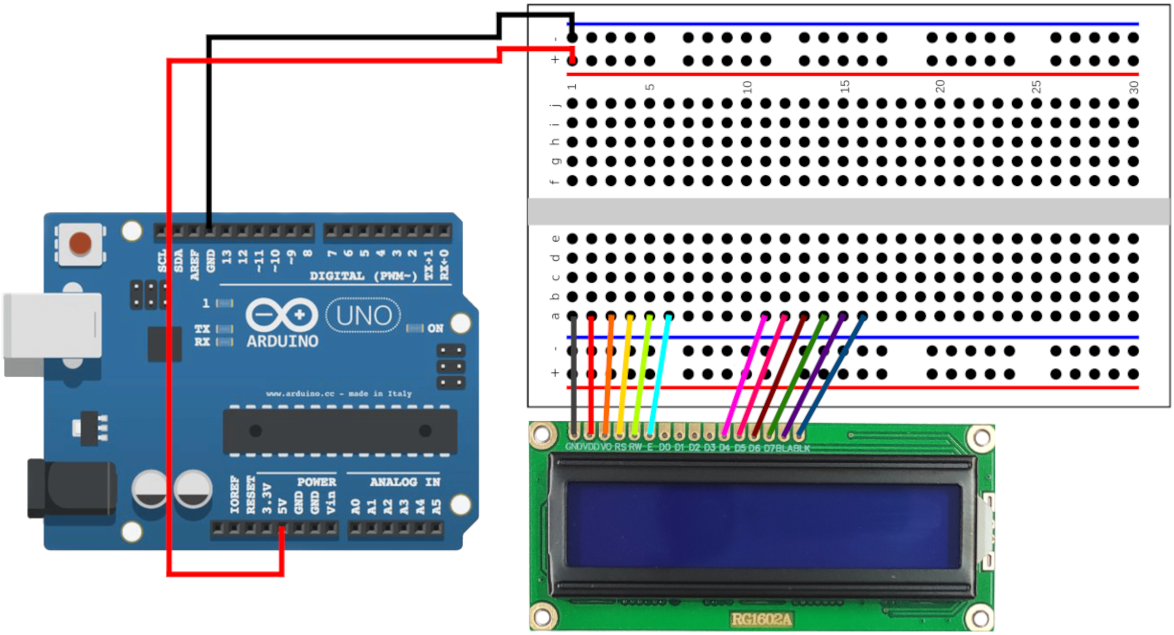
In the diagram provided, while all the pins of the LCD are inserted into the breadboard, this project will not utilize the LCD's "D0", "D1", "D2", and "D3" pins (they're optional and have special use cases on certain configurations).
Now we're ready to connect jumper wires and build a circuit that connects the LCD to the Arduino board via the breadboard.
The LCD has a "VSS" (Voltage Supply Ground) or a "GND" (Ground) pinned at the "a1" coordinate of the breadboard. Grab a jumper wire and pin one end to the "e1" coordinate of the breadboard. Pin the other end to any of the hole in the "-" column of the breadboard.
The LCD has a "VDD" (Voltage Supply Drain) or "VCC" (Voltage Supply Collector) pinned at the "a2" coordinate of the breadboard. Grab a jumper wire and pin one end to the "e2" coordinate of the breadboard. Pin the other end to any hole in the "+" column of the breadboard.
The LCD has a "RS" (Register Select) pinned at the "a4" coordinate of the breadboard. Grab a jumper wire and pin one end to the "e4" coordinate of the breadboard. Pin the other end to the Arduino board's pinhole number 12.
The LCD has a "RW" (Read/Write) pinned at the "a5" coordinate of the breadboard. Grab a jumper wire and pin one end to the "e5" coordinate of the breadboard. Pin the other end to any of the hole in the "-" column in the breadboard.
The LCD has a "E" (Enable) pinned at the "a6" coordinate of the breadboard. Grab a jumper wire and pin one end to the "e6" coordinate of the breadboard. Pin the other end to the Arduino board's pinhole number 11.
The LCD has a "D4" pinned at the "a11" coordinate of the breadboard. Grab a jumper wire and pin one end to the "e11" coordinate of the breadboard. Pin the other end to the Arduino board's pinhole number 5.
The LCD has a "D5" pinned at the "a12" coordinate of the breadboard. Grab a jumper wire and pin one end to the "e12" coordinate of the breadboard. Pin the other end to the Arduino board's pinhole number 4.
The LCD has a "D6" pinned at the "a13" coordinate of the breadboard. Grab a jumper wire and pin one end to the "e13" coordinate of the breadboard. Pin the other end to the Arduino board's pinhole number 3.
The LCD has a "D7" pinned at the "a14" coordinate of the breadboard. Grab a jumper wire and pin one end to the "e14" coordinate of the breadboard. Pin the other end to the Arduino board's pinhole number 2.
The LCD has a "A" or "BLA" (Anode) pinned at the "a15" coordinate of the breadboard. Grab a jumper wire and pin one end to the "e15" coordinate of the breadboard. Pin the other end to any of the hole in the "+" column of the breadboard.
The LCD has a "K" or "BLK" (Cathode) pinned at the "a16" coordinate of the breadboard. Pin the other end to any of the hole in the "-" column of the breadboard.
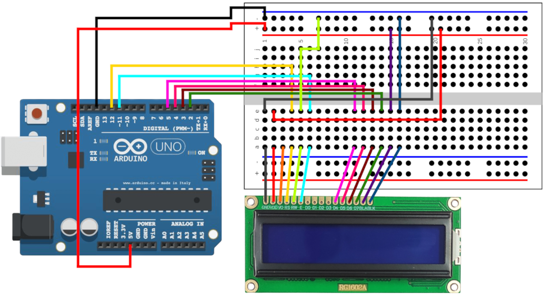
Following the previous steps, the breadboard has become crowded with jumper wires. However, our task is not complete. Next, we will address the "VO" (Voltage Output) pin of the LCD pinned at "a3" coordinate of the breadboard, which we have yet to utilize.
Before moving on to the next step, verifying that the wires are correctly connected is crucial. Connect the Arduino board to a power source; the LCD should light up. If it doesn't, then an issue must be addressed.
Installing the Potentiometer
Another essential component of the LCD is the potentiometer. This small device, either cylindrical or rectangular, comes with three pins. It features a knob, often referred to as a "wiper," which can be turned either clockwise or counterclockwise. The potentiometer essentially acts as a variable resistor, regulating the flow of electricity through its rotation. Its applications are diverse, including volume and speed control, and positioning sensors, among others. In the context of an LCD module, the potentiometer adjusts the screen's contrast level.
The next step is to install the potentiometer. We will connect jumper wires directly to the potentiometer due to the limited space remaining on the breadboard. Nonetheless, employing a potentiometer with a larger breadboard is feasible and can be explored as a separate exercise.
The LCD has a "VO" (Voltage Output) pinned at the "a3" coordinate of the breadboard. Grab a jumper wire and pin one to the "e3" coordinate of the breadboard. Attach the other end to the middle pin of the potentiometer.
We need to supply power to the potentiometer. Grab a jumper wire and attach one end to the left pin of the potentiometer. Pin the other end to any of the pinhole in the "+" column of the breadboard.
We need to set the ground of the potentiometer. Grab a jumper wire and attach one end to the right pin of the potentiometer. Pin the other end to any of the pinhole in the "-" column of the breadboard.
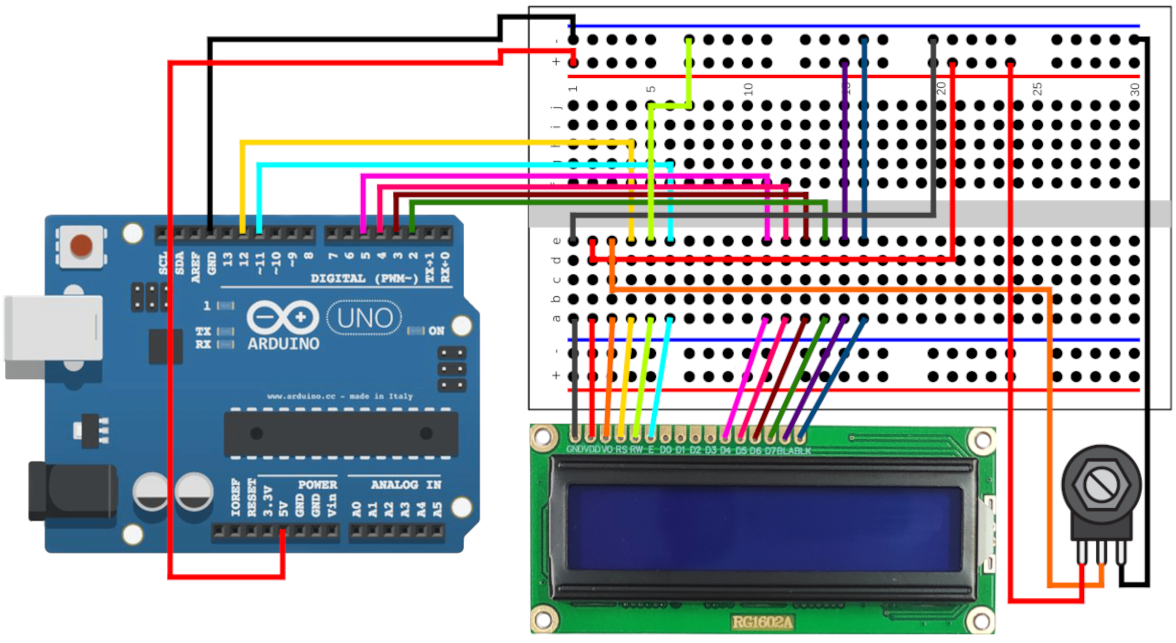
To check the functionality of the potentiometer, rotate the knob (also referred to as the wiper) back and forth. If the wiring is correct, the LCD's contrast will vary accordingly.
Writing the Source Code
We will now write code to display text on an LCD. It's important to note each pin on the LCD and the corresponding pinhole number it connects to on the Arduino board. These pinhole numbers will be used in the source code.
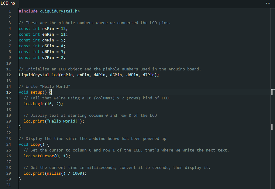
After verifying and uploading the code to the Arduino board, text should appear on the LCD screen. Adjust the LCD's contrast using the potentiometer to ensure text visibility.
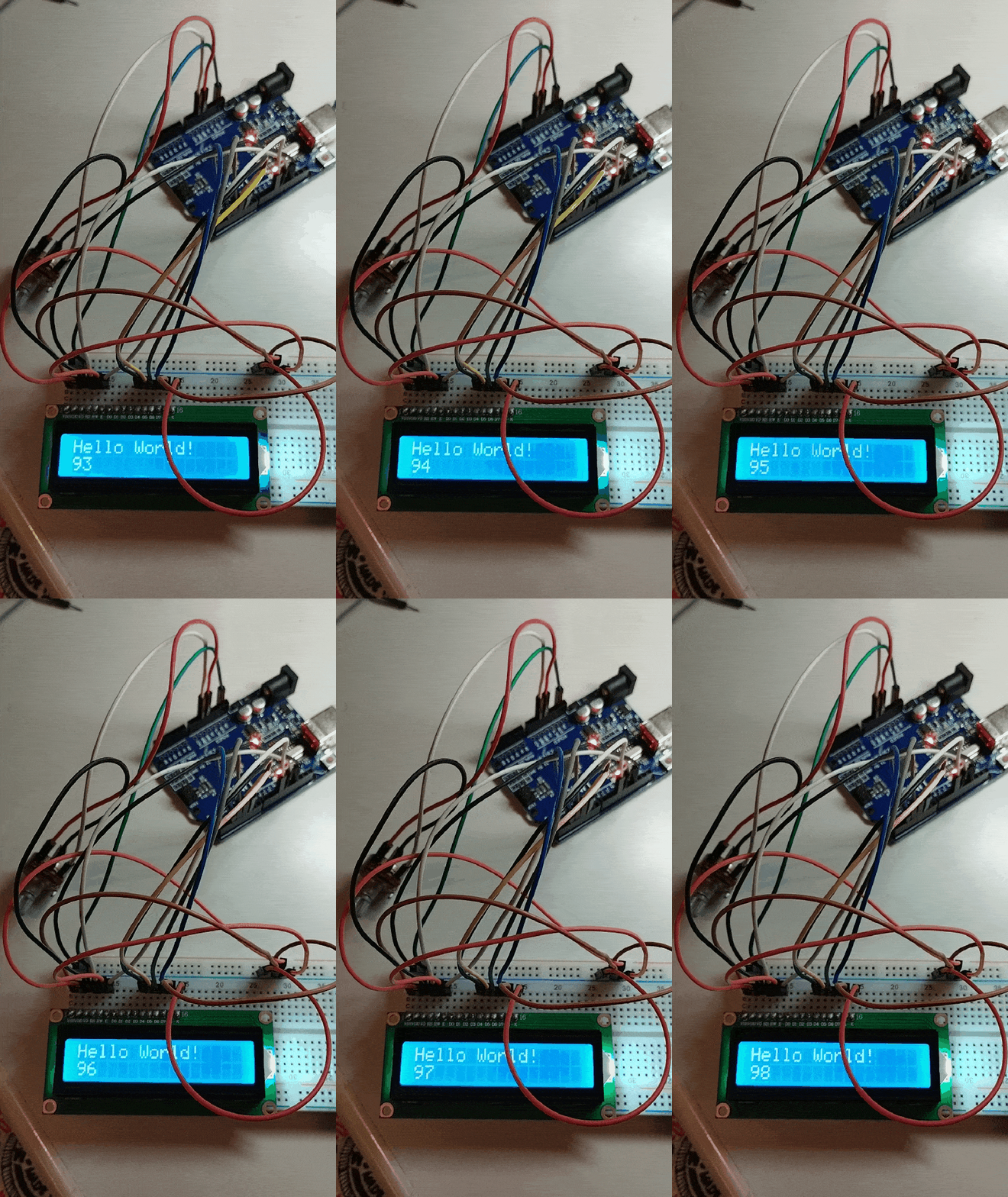
That's a concise overview of LCD capabilities. Additionally, the LCD module offers functionalities like text scrolling, light blinking, and custom character displays, among others. These features can be explored further by consulting the LiquidCrystal library's documentation.