

Objectives
This chapter will explain the use of a relay module with a straightforward demonstration to highlight its significance.
The DC Motor
While DC motors are unrelated to relay modules, understanding the concept of a DC (Direct Current) motor is beneficial before examining relay modules, as it will facilitate a better grasp of the demonstration.
A DC motor is a device that rotates upon receiving power. It is frequently utilized in projects for rotating gears, and wheels, or even serving as an electric fan.
In this demonstration, we will use a 5v DC motor that can be powered by an Arduino board.
Grab a jumper wire and connect one end to one of the DC motor's pin. Pin the other end to Arduino Uno's GND (Ground) pinhole.
Take a jumper wire and attach one end to the other pin of the DC motor. Connect the other end to the 5v pinhole on the Arduino Uno.
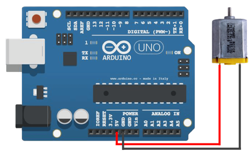
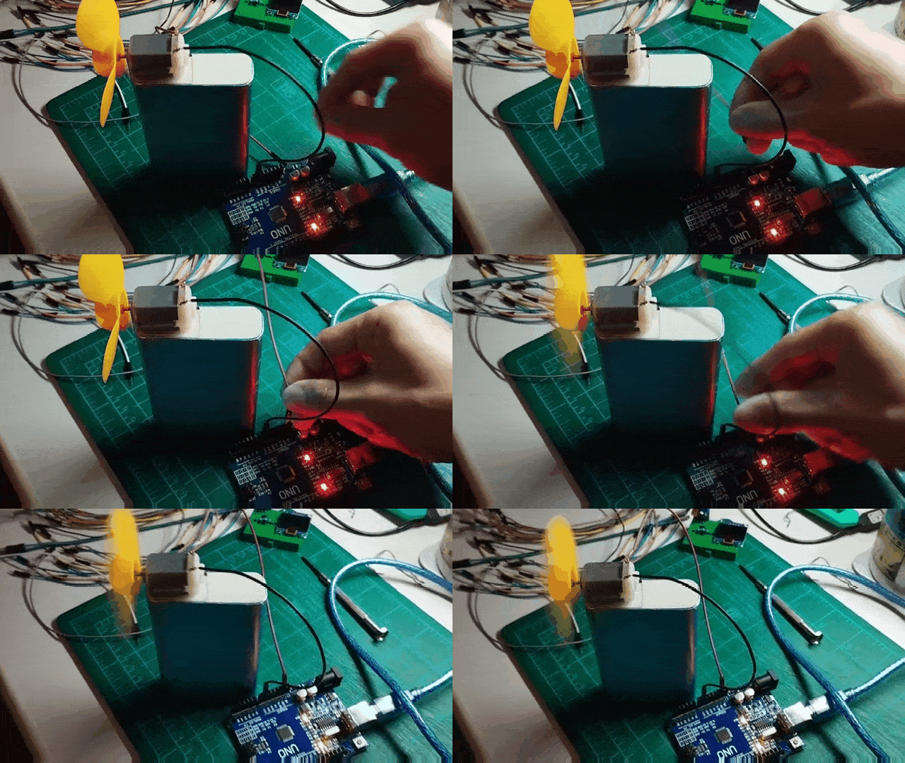
Once you have connected the DC motor to the Arduino board, the motor should begin to spin.
Programmatically Controlling the DC Motor
To control the DC motor's on and off states, disconnect the wire from the 5v supply and connect it to a digital pin. This connection enables us to control the DC motor programmatically, allowing it to start and stop on command.
Disconnect the jumper wire connected to the 5v pinhole of the Arduino board.
Plug the disconnected jumper wire to pinhole 2 of the Arduino board.
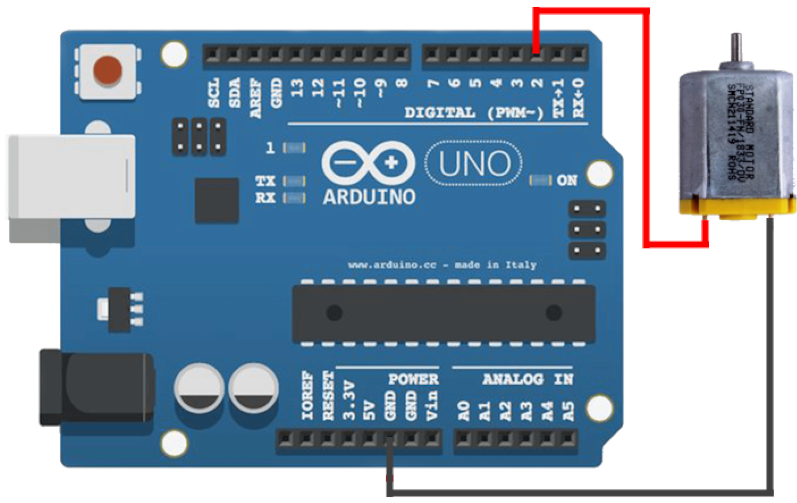
Next, we'll write a code that turns the motor on after every 1 second.
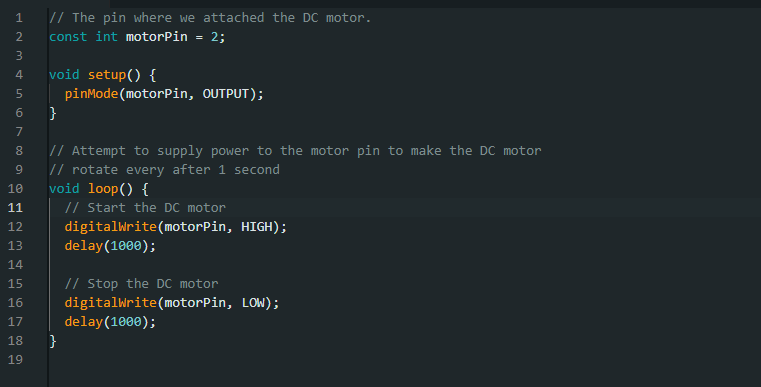
If we attempt to verify and upload the code to our Arduino board, we will notice that the DC motor is not rotating at all.
The Problem
The DC motor fails to operate when powered through a digital pin due to insufficient amperage. While the digital pins of an Arduino can provide 5 volts, it is limited to draw a current of up to 40 milliamperes. A 5v DC motor requires 50 to 100 milliamperes to operate, which is why we cannot power it directly from an Arduino's digital pin.
For a clearer understanding, consider a water pipe analogy: voltage is akin to the pressure of water flowing through the pipe, and amperage corresponds to the amount of water that the pipe can carry.
The Solution: Relay Module
A relay module serves as an intermediary to control a device like a DC motor. The process is straightforward: we attach the relay module to the Arduino board and connect the DC motor to the relay module. This setup allows us to control the relay module programmatically, enabling or disabling it as needed. When activated, the relay permits electrical current to flow through the DC motor.
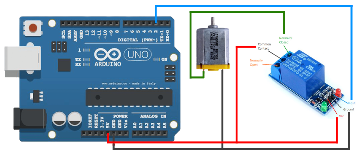
The relay module has 6 connections:
VCC (Voltage Supply Collector) or VDD (Voltage at the Drain): This should connect to a 5v power source to power up the relay module,
GND (Ground): The ground reference where current exits in the circuit,
IN (Input)I: The pin that allows us to programmatically activate or deactivate the relay module,
NO (Normally Open): Refers to a connection point where the power source of a device, such as a DC motor, is attached so that power is supplied by default,
NOC/NC (Normally Closed): Refers to a connection point where the power source of a device, such as a DC motor, is attached so that no power is supplied by default, and
COM (Common Contact): Refers to a connection point for the power source of a device that will flow either to NO or NC/NOC slots depending on the status of the relay module (activated/deactivated).
Building the Circuit
We will now do a hands-on exercise to construct a circuit using a relay module along with a DC motor.
Grab a jumper wire and connect one end to one of the DC motor's pin. Pin the other end to Arduino Uno's GND (Ground) pinhole.
Grab a jumper wire and attach one end to the other pin of the DC motor. Connect the other end to the NOC/NC (Normally Closed) slot of the relay module.
Grab a jumper wire and attach one end to the 5v pinhole of the Arduino board. Connect the other end to the COM (Common Contact) slot of the relay module.
Grab a jumper wire and attach one end to the GND (Ground) pinhole of the Arduino board. Connect the other end to the GND (Ground) pin of the relay module.
Grab a jumper wire and attach one end to the 5v pinhole of the the Arduino board. Connect the other end to the VCC (Voltage Supply Collector) pin of the relay module.
Grab a jumper wire and attach one end to pinhole 2 of the Arduino board. Connect the other end to the IN (Input) pin of the relay module.
The Source Code
Next, we'll write a code that turns the motor on the motor after every 1 second.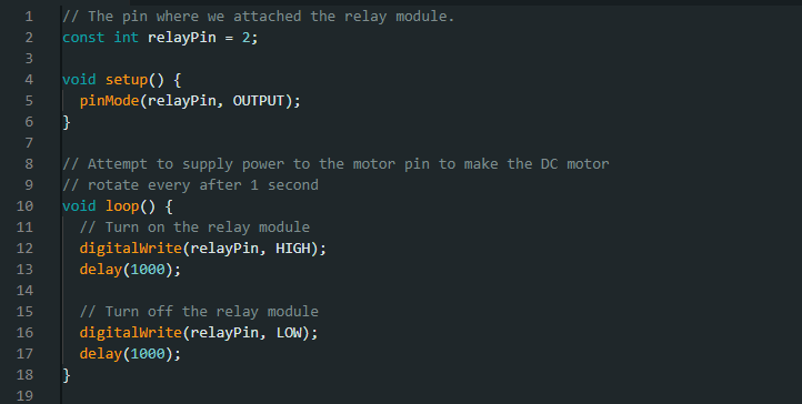
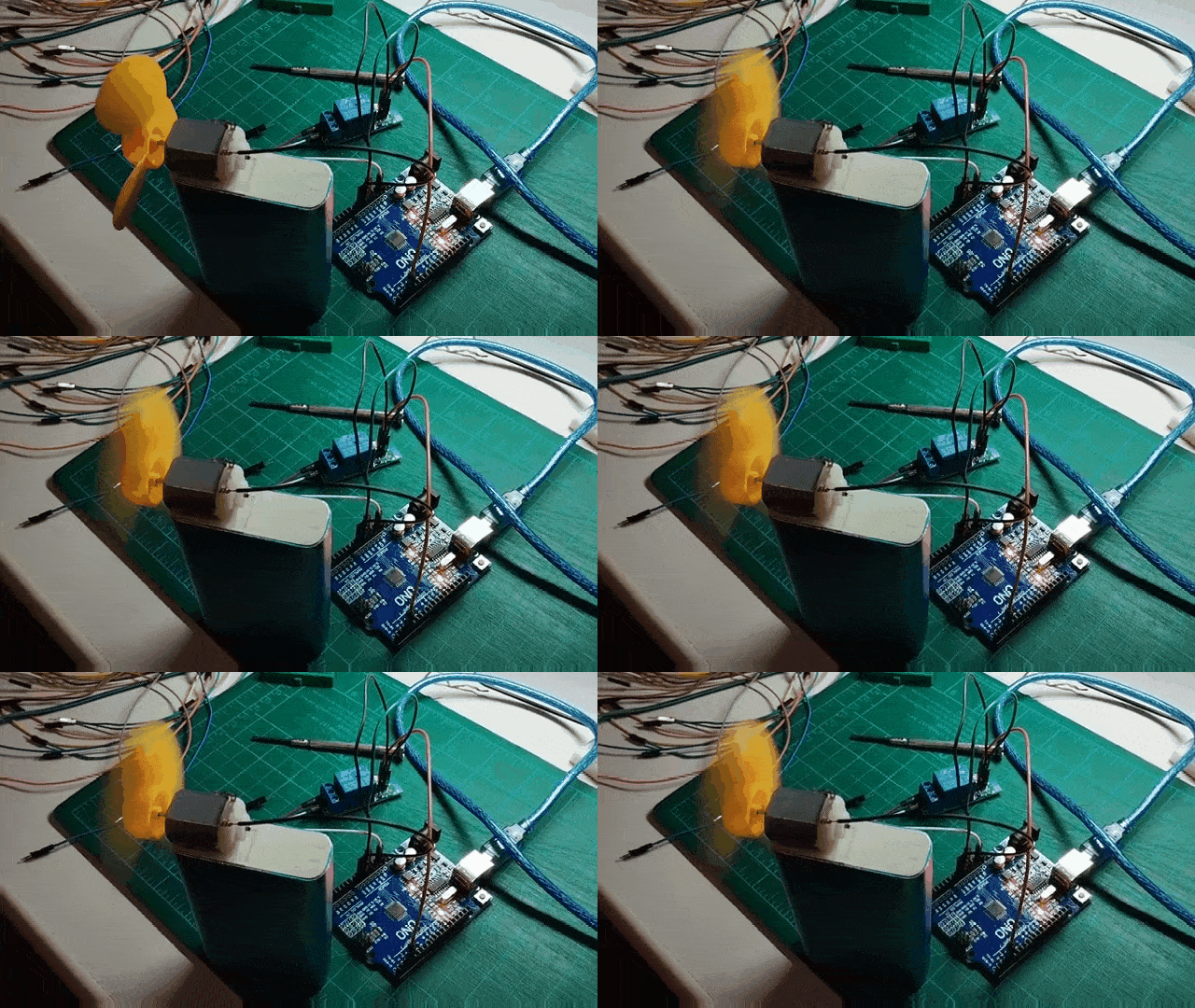
Verify and upload the source code to the Arduino board, and the motor should rotate, pausing after each second.
Caution!
The Arduino Uno board has a total current supply limit of 300 to 400 milliamperes. Exceeding this limit can result in damage to the board. The demonstration's current setup, which includes a relay module and a single DC motor, operates safely within this limit. However, adding additional modules and sensors that rely on the Arduino for power is not advisable.
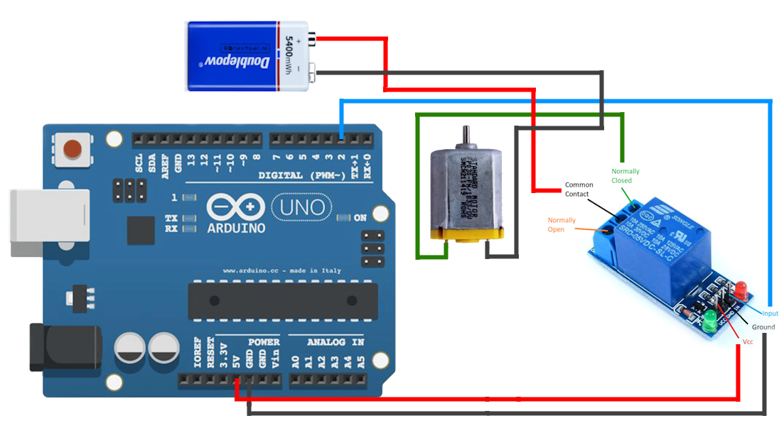
We can improve our demonstration by using a separate power supply (9v Battery) for the DC motor to free up the Arduino board. Kindly refer to the diagram below.
Moving Forward
Numerous projects can benefit from the use of a relay module; however, it's crucial to recognize that various devices require different voltages and amperes. Consequently, there are different types of relay modules designed to meet varying requirements. With this in mind, we must always check the voltage and ampere specifications to ensure compatibility between the device and the relay module, as a mismatch could lead to damage and accidents.
Generally, voltages exceeding 50 volts may be hazardous and potentially lethal, so it is advisable to seek guidance from a certified electrical engineer when handling projects that involve high voltages.