

Objectives
This chapter will explore the joystick module, an input device designed to control movements by physically moving a lever. The discussion will cover practical applications, the wiring process of a joystick in an Arduino project, and the essential source code required to retrieve data from the joystick.
Prerequisites
Setup
Joystick
Arduino Uno board
Jumper Wires
About the Joystick
A joystick has a lever that we can push in any direction. Since we're talking about directions, we will have X (horizontal) and Y (vertical) coordinate values.
In previous chapters, we've explored using potentiometers for tasks like adjusting sensor detection sensitivity or display contrast. This chapter will introduce another application of potentiometers, focusing on their role in joystick control.
Inside the joystick are two potentiometers; one controls the X-axis values, while the other manages the Y-axis values. As the joystick's lever is pushed, these potentiometers alter electronic signals to produce the corresponding X and Y coordinate values, offering Arduino programmers a chance to use this information creatively.
In addition to pushing the joystick's lever, the joystick can also be pressed down like a button, which should produce a clicking sound. This occurs because there is a switch button beneath the joystick. When this button is pressed, it generates an electronic signal that indicates its current state. This signal can be captured within the source code, allowing Arduino programmers to utilize this information creatively.
Considering the mentioned features of the joystick, it can serve various functions, including as a game controller, for menu navigation, as a remote controller, and much more.
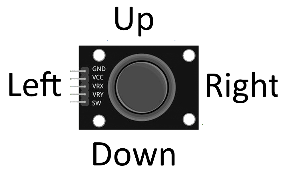
The joystick module requires four pins to function and they are:
VCC (Voltage Supply Collector): Should connect to a 5v power source to let power flow to the joystick,
GND (Ground): The ground reference where current exits in the circuit,
VRx (Variable Resistor X-axis): Allows to read analog value from the joystick while being pushed horizontally,
VRy (Variable Resistor Y-axis): Allows to read analog value from the joystick while being pushed vertically, and
SW (Switch Pin): Allows to read the state of the joystick if pressed.
Building the Circuit
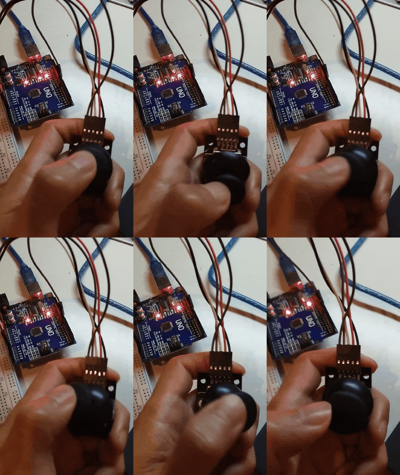
Now we do a hands-on exercise by building a circuit with a joystick. To simplify this exercise, we'll skip the breadboard and directly connect the jumper wires from the Arduino board to the joystick. Nevertheless, a breadboard can always be utilized as a separate exercise.
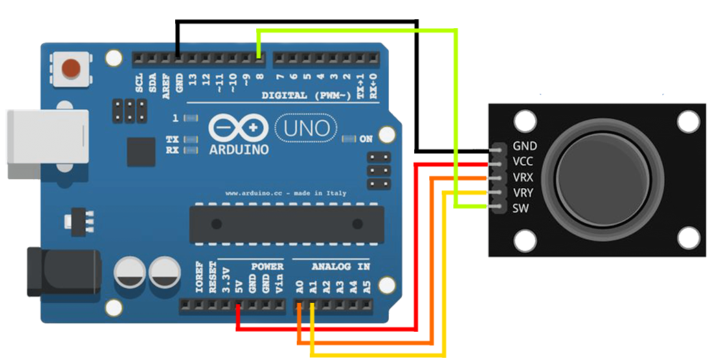
Grab a jumper wire and connect one end to the joystick's "VCC". Pin the other end to Arduino Uno's "5v" (Power Supply).
Grab a jumper wire and connect one end to the joystick's "GND". Pin the other end to Arduino Uno's "GND" (Ground).
Grab a jumper wire and connect one end to the joystick's "VRx". Pin the other end to Arduino Uno's "A0" (Analog Input 0).
Grab a jumper wire and connect one end to the joystick's "VRy". Pin the other end to Arduino Uno's "A1" (Analog Input 1).
Grab a jumper wire and connect one end to the joystick's "SW". Pin the other end to Arduino Uno's pinhole number 8.
Different pinhole numbers can be utilized on the Arduino board, but it is crucial to connect "VRx" and "VRy" to analog pinholes and "SW" to a digital pinhole. It is important to note the pinhole numbers used, as they will be referenced in the source code later.
Writing the Source Code
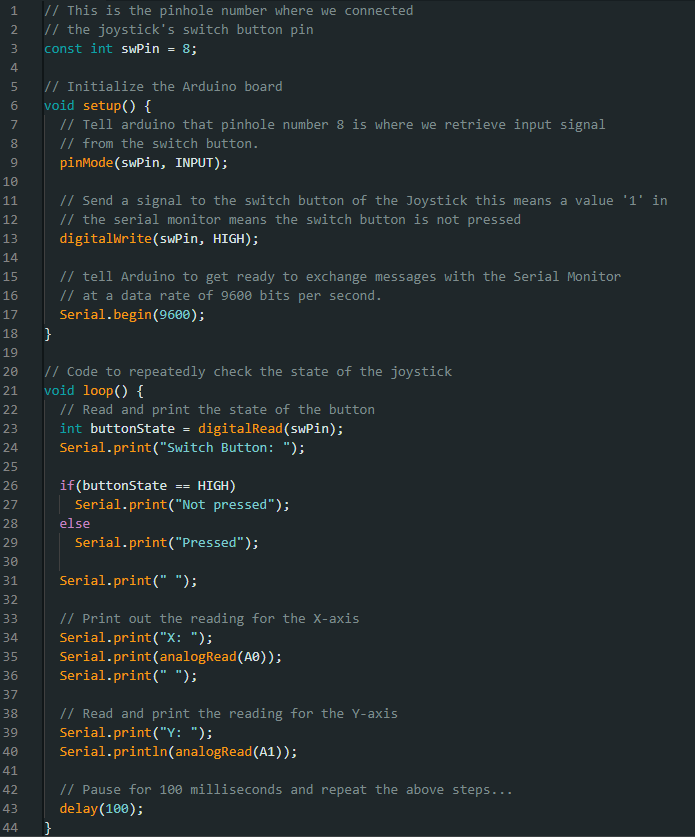
Next, we will write a source code that captures the X and Y axis values generated by the joystick and its current press state.
After verifying and uploading the code to the Arduino board, the Serial Monitor should display an output indicating the state of the joystick.
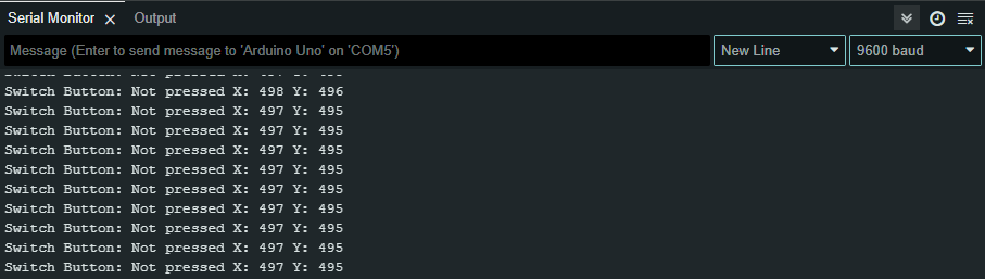
The above output shows that the X and Y axis values range from 400 to 500, suggesting that the joystick's lever is neutral.
Now, we try moving the joystick in various directions to observe the changes in the X and Y axis values.
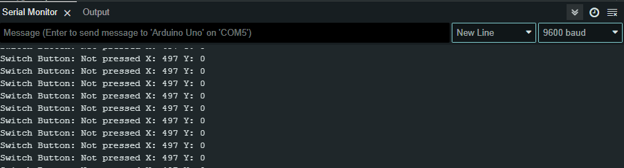
Moving the joystick upwards will reduce the Y-axis value to 0.
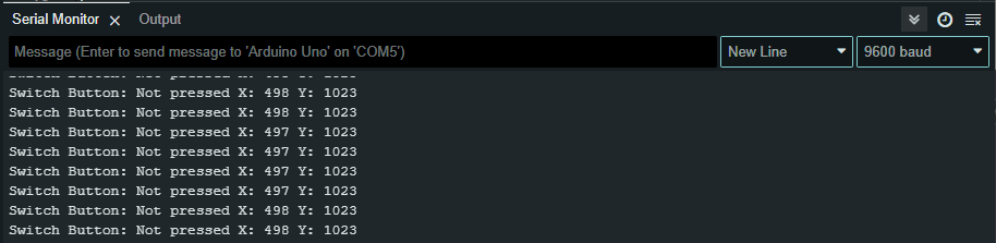
Moving the joystick downward will increase the Y-axis value to 1023.
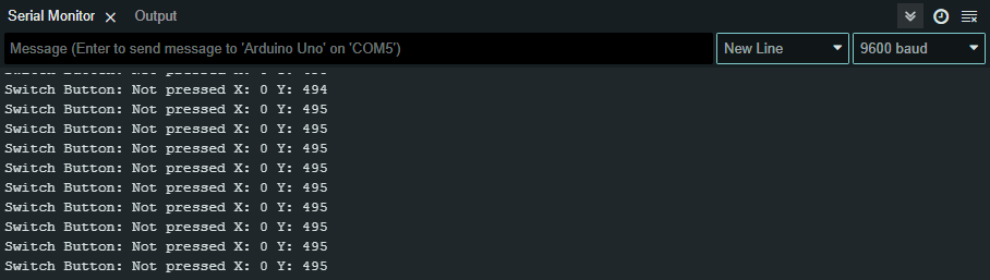
Moving the joystick to the left will reduce the X-axis value to 0.
Moving the joystick to the right will reduce the Y-axis value to 1023.
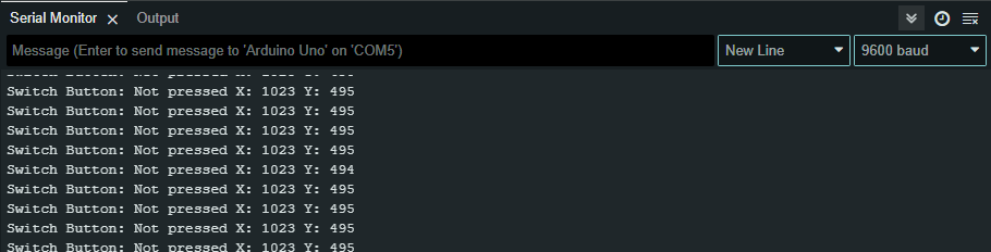
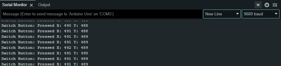
Holding down the joystick will trigger the switch button.
A joystick's movement is not confined to just the up, down, left, and right directions; it can also be rotated in a circular motion, enabling the X and Y axis values to vary between 0 and 1023.