

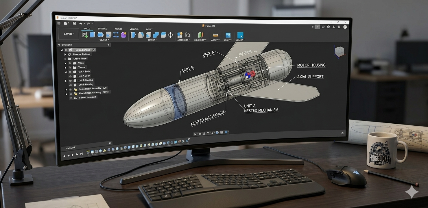
In the last post, we took the Mosquito from a bad idea to a simulated one. We figured out the scale, set the intent, picked materials, and got the numbers close enough to start feeling dangerous. Now comes the part where the rocket stops being theoretical and starts making demands: CAD. This is where a lot of builders hit the wall, because there are about a thousand ways to get from simulation to a real model, and every designer has their own workflow, religion, bad habits, and favorite flavor of suffering. You can export .obj geometry straight out of OpenRocket if you want the most literal interpretation of the sim, and that’s a perfectly valid path, but it isn’t usually mine. OpenRocket gives me an accurate picture of the rocket. CAD is where I decide what that rocket actually needs to become buildable, printable, strong enough, and honest about the materials we’re really working with.
That also means CAD doesn’t get to wander off on its own little side quest. As I flesh out the real design, I have to keep circling back to the simulation and updating it so the two models don’t drift apart. The CAD represents the actual rocket I intend to build. The simulation represents the rocket’s behavior in flight. If those two stop matching, then I’m not simming the rocket I’m actually building, and that’s how you talk yourself into dumb surprises. Aim small, miss small.
Project Setup and Parameters
When I start laying this out in Fusion 360, I think about it a little like NASA assembling a rocket in the Vehicle Assembly Building. One file, all the major parts, everything living in one place where I can see how the system goes together. I usually build from the top down, and each part lives as its own component. For this project, the mental map starts with the big obvious pieces: Nosecone, Body Tube, Fin, Centering Rings, Retainer, and Ebay
They don’t have to be in that order. CAD doesn’t care. That order is mostly for me. It’s a mental map more than a technical requirement, and it helps keep the project from turning into a junk drawer full of mystery bodies and sketches. I try to keep parts as separate components whenever I can, because I want to see the structure clearly, isolate problems quickly, and avoid repeating myself when one change starts rippling through the design.
Once the component skeleton is there, I usually open the parameters window and start entering the values I know are going to matter. Parameters mostly work for me because they let me change key dimensions without rebuilding the whole rocket every time I learn something new or realize I lied to myself three sketches ago. They help keep related geometry consistent, make iteration less painful, and are especially useful when you already know some dimensions are going to move as the design gets more honest.
That said, I don’t parameterize everything just because I can. That’s a great way to build yourself a very smart, very fragile mess. Keep it simple, spaceman. I usually limit parameter use to the nosecone and the body tube or motor mount tube values, because those are the dimensions most likely to affect a lot of downstream geometry. Beyond that, I’d rather stay disciplined than clever.
Nosecone
Where do I start? Usually at the top. I almost always begin with the nosecone. Even though the body tube is really the center-line of the design, once I have the body tube parameters defined, I can build the nose without painting myself into a corner later.
For nosecones, I generally use one of two approaches.
Sketch it by hand. This is a great skill to have because most CAD systems won’t do this for you. Also, nosecones like The Der Red Max have such a signature shape that you’re going to have to get into the toolbox to reproduce them properly.
Use a nosecone generator. One of my favorites is the plugin by Dave at Dave’s Rocket Shop. That Dave isn’t this Dave, but in my experience, most Daves are generally pretty cool. Hi, Dave. The plugin gets you most of the way where you want to go, and it’s available in both Fusion 360 and FreeCAD through Rocket Workbench, which is handy. Thanks, Dave!
That brings me to a few design rules I try to follow.
Rule #1: Don’t repeat yourself. If you design a part like an avionics sled or a motor retainer, design it so you don’t have to reinvent it every single time. Most of my rockets reuse the same retainers, tailcones, and AV sled concepts, just scaled for the airframe I’m working on. I keep core designs for each common size I build, so I’m not spending five hours re-tweaking the same part for the fifth time, like some kind of CAD groundhog day.
Rule #2: Keep it simple, spaceman. Or spacewoman. Or space-individual. Astronaut? No, that loses the plot. The point is: keep it simple. Building rockets is rocket science. There are already plenty of things waiting downstream that can go sideways. If you start adding a bunch of cute details too early, there’s a good chance they’re going to come back later and kick you directly in the fan-knee.
Rule #3: Be thoughtful about material choice when you design. You need to understand how the material is going to behave in the context of the design. For example, balsa would be awesome for this rocket because of the weight, except it’s probably the worst possible choice because of its strength.
Fin Design
The fin for this model is deceptively complicated. Upscaling a rocket always brings a few weird little gifts, and this fin is one of them.
The first problem is that I can’t design the fin in a vacuum. I have to think about how it’s actually going to be manufactured while I’m drawing it. In theory, this fin could be made out of plywood, fiberglass, carbon fiber, or as a printed part. Each one changes the design conversation.
I usually start by opening the fin definition in OpenRocket. The Mosquito uses a manually laid-out fin profile, which is good enough for getting close to the original shape but not especially friendly when it comes time to move it into CAD. So I pull the coordinates from the sim, sketch the rough profile, and use a 3-point arch to tie the trailing geometry together, followed by a lot of fiddly fadoodling to get it to look right. Also, no airfoils here, for reasons I’ll get into in the next post. Annoying, yes. Easy? Also, yes, compared to what came next.
Once the shape existed, the real problem showed up. This fin comes out to about 85.9 mm (3.3 in) wide, 391 mm (15.4 in) long, and 6.35 mm (0.25 in) thick. Yikes! Print that as a single fin in regular PETG or ASA, and it’s going to be too flexible and too vulnerable when it hits the ground with bad intent. So now we get to the real question: what are my actual options?
• Cut it from plywood. Perfectly reasonable, but I don’t currently have a good way to do that cleanly.
• Cut it from fiberglass or carbon fiber. Also solid choices, but harder materials, messier workflow, and I still don’t have a practical way to cut them.
• Print the fin in one piece. Massive on the print bed (if printing), challenging to print in ASA/ABS, and it breaks my 256-cubed rule anyway.
• Split the fin and join it later. Better.
• Print the fin as a router template. Honestly, this is probably the best option if I want plywood fins without a lot of suffering.
I decided on a hybrid of the split-fin approach. I’ll get into the weeds on that later, but I used OrcaSlicer to split the fin width-wise at a 45-degree angle from the top plane. I also used the dovetail join option with the split tool, keeping the dovetail thick and away from the edges, which gave me a compound dovetail joint, a really strong dry joint, and a lot more adhesive surface area to work with. This was my final fin geometry decision. PSYCH!
The fin had me worried. Any time there’s a break in a printed part, that break becomes a potential weakness, so I stopped theorizing and just printed the thing. More than once, actually. The good news was that the dovetail joint felt strong, solid, and a lot less sketchy in the hand than it did in my head. The bad news was the overall length. This fin is ridiculous. Long enough to be awkward, cumbersome, and generally hateful to work with. If I hadn’t already opened my big mouth in Part 1 about doing my Level 2 with this rocket, I might have abandoned the idea and gone off to design something else. Probably an upscale Black Fly. Oh wait, I already did that. Damn.
What kept nagging at me was that even after joining the fin, it was still too flexible. It wobbled back and forth, and there just wasn’t enough strength in the long dimension. So I did what I usually do when a design starts annoying me: I sat with it, thought about it, and started stealing ideas from other hobbies. Back when I was building model airplanes, spars were the answer for wing stiffness. That got me wondering if I could borrow the same idea here.
The next problem was figuring out what I could shove into this thing to add stiffness without paying a huge mass tax. I needed something light, stiff, and small enough to fit inside a fin that’s only 6.35mm thick. My first attempt was a single 3mm solid carbon fiber rod running down the center. Surely that would do it, right? Spoiler alert: no, it wouldn’t. And never call me Shirley.
This is where the nerd content kicks in. Rocket science is engineering, sure, but it’s also material science, physics, chemistry, a little bit of art, and a lot of imagination. I iterate a lot: design, print, test, break, cuss, redesign, then rinse and repeat until the part in my hand starts looking like the part I thought I had in my head.
So I went back into CAD and bored a channel straight down the middle of the fin. Better, but still too floppy. Back to CAD. This time, I added two more channels, one on each side of center, and tried again. That was the turning point. Those bores effectively created stiffening tubes inside the fin, and once I added the carbon fiber rods, the rigidity improved enough that the whole thing started feeling credible.
Between boring holes for carbon fiber spars and auditioning materials, I printed a stupid number of fin variations. I worked through several filament types, researching each one and then printing test parts. A few engineering-grade filaments worked… meh, okay, but I eventually landed on ABS-GF. It gave me the strength I needed, minimal shrinkage (everyone hates shrinkage), reasonable cost, good availability, a great print finish, and excellent stiffness in every dimension that mattered. Was it perfect? No. But it got me close enough to the goal line without needing a grant from the National Science Foundation. At that point, the fin finally felt solid enough that I’d trust it on a Level 2 flight.
I also custom-designed locking centering rings and added a 54 mm motor retainer, and either one of those could easily become its own post. If I stop to fully unpack every part here, this series will still be going when the Sun burns out. So, for now, I’m going to keep moving. If you want to see how those pieces were built, drop a comment, and I can break them out later. You’ll get to see all the bits in the build portion of this series.
Wrap-Up
That is probably enough CAD carnage for one post. The point of this stage was never to make the rocket pretty. It was to make it real.
OpenRocket got me to believable dimensions and performance targets, but CAD is where those numbers had to survive contact with materials, print limits, joints, tolerances, and my own bad decisions. This is where the design stops being a sketch and starts becoming a thing that has to justify itself.
That’s really the whole game here. Keep the CAD and the sim aligned. Don’t repeat yourself. Keep it simple, spaceman. Be honest about your materials. The rocket doesn’t care that you meant well, made something sexy, or felt like an absolute wizard in CAD at 1:30 in the morning. It will find every weak assumption, every very lazy shortcut, and every little lie you told yourself, then expose them in front of your launch safety officer and the rest of the club. Not because it hates you, but because that’s what rockets do. If you’re lucky, you won’t end up on a YouTube “Rocket Fails” video.
In the next installment, I’ll move from CAD into the equally critical world of slicing, print orientation, and material strategy. The printer doesn’t care how good the design looked in CAD. It will expose flaws, punish bad decisions, and occasionally invent brand-new problems just to keep things interesting. Slicers can smell fear, and next time we’re going to find out exactly how much I’m broadcasting.