Ripple Radios
2,535 seguidores
Iniciar sesión
Iniciar sesión
Ripple Radios
Publicaciones
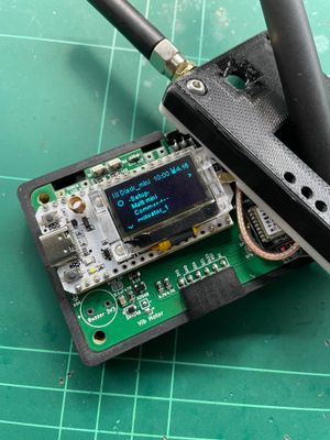
Build Guide: BLE Pager
Build Guide: BLE Pager
Jul 17, 2024
Compartir
¿Te gusta esta publicación?
Comprar Ripple Radios un café
Apoyo
Compartir
Más de Ripple Radios
Item 1 of 1
Español
English
Deutsch
Español
Italiano
Français
Українська
Privacidad
Condiciones
Denunciar
Empieza tu página de Buy Me a Coffee