
Objectives
This chapter will discuss how to wire a sound sensor for an Arduino project. The sound sensor module captures sound and converts it into electrical signals. These signals can be programmatically utilized for various projects, including sound-activated lights, noise level monitoring, and sound-controlled devices.
Prerequisites
Setup
KY-038 Sound Sensor
Arduino Uno board
Jumper Wires
About the Sound Sensor
The sound sensor is composed of a microphone that detects sound levels. As more of the sensor detects sound, it generates a stronger electrical signal. This signal can be captured and applied in our Arduino projects for various purposes.
The sound sensor requires four pins to function and they are:
+ (Voltage Supply Collector): Should connect to a 5v power source to power up the sensor.
GND (Ground): The ground reference where current exits in the circuit.
DO (Digital Output): Allows Arduino to obtain digital data from the sensor, returning a value of 1 when a sound is detected and 0 when no sound is present.
AO (Analog Output): Allows the Arduino to obtain analog data from the sensor, typically between 0 and 1023. The greater the amount of sound captured, the higher its value.
Building the Circuit
We will now do a hands-on exercise to build a circuit using a sound sensor.
Snap the sound sensor's pins to the breadboard. Put the first pin of the sound sensor in the "f1" coordinate of the breadboard. Since we cannot separate pins in the sound sensor, this would mean that the next 3 pins would occupy the coordinates "f2", "f3", and "f4" of the breadboard. We assume here that:
Coordinate "f1" points to the "AO" pin of the sound sensor
Coordinate "f2" points to the "GND" pin of the sound sensor
Coordinate "f3" points to the "+" pin of the sound sensor
Coordinate "f4" points to the "DO" pin of the sound sensor
Grab a jumper wire and pin one end to the "j1" coordinate of the breadboard. Pin the other end to Arduino's "A0" pinhole.
Grab a jumper wire and pin one end to the "j2" coordinate of the breadboard. Pin the other end to Arduino's "GND" pinhole.
Grab a jumper wire and pin one end to the "j3" coordinate of the breadboard. Pin the other end to Arduino's "5v" pinhole.
Grab a jumper wire and pin one end to the "j4" coordinate of the breadboard. Pin the other end to Arduino's pinhole number 2.
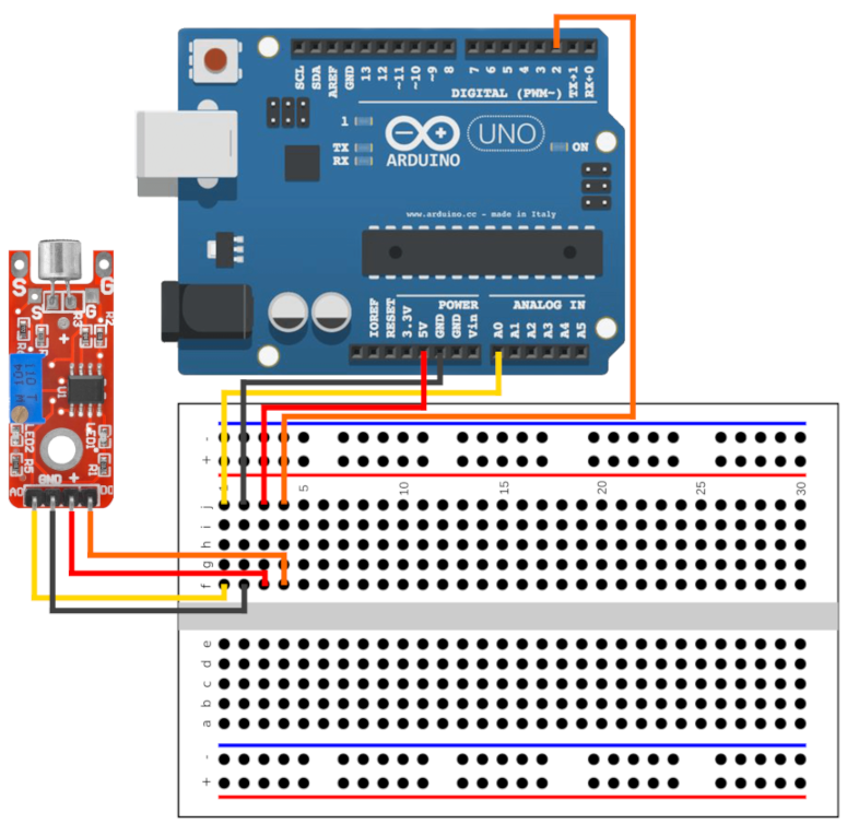
In this demonstration, we utilized pinhole "A0" for "AO" and pinhole number 2 for "DO". While other analog and digital pinholes are technically viable, it's crucial to note the specific ones in use, as we will need to specify pinhole "A0" and pinhole number 2 later in the code.
Sound sensors commonly have two integrated LEDs: one that lights up when powered and another that activates upon detecting sound. These sensors are equipped with a potentiometer, which can be adjusted to modify the sensitivity of sound capture.
Writing the Source Code
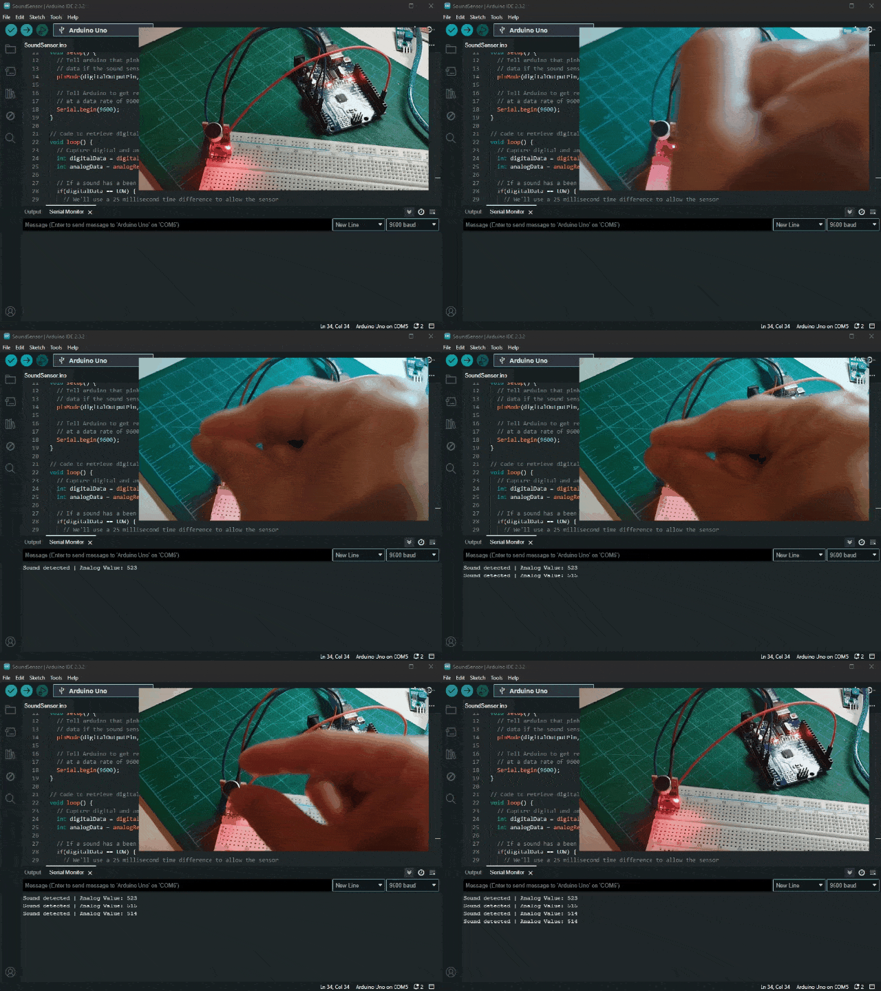
Next, we will write code that checks if the sound sensor captures sound, it then displays it on the Serial Monitor.
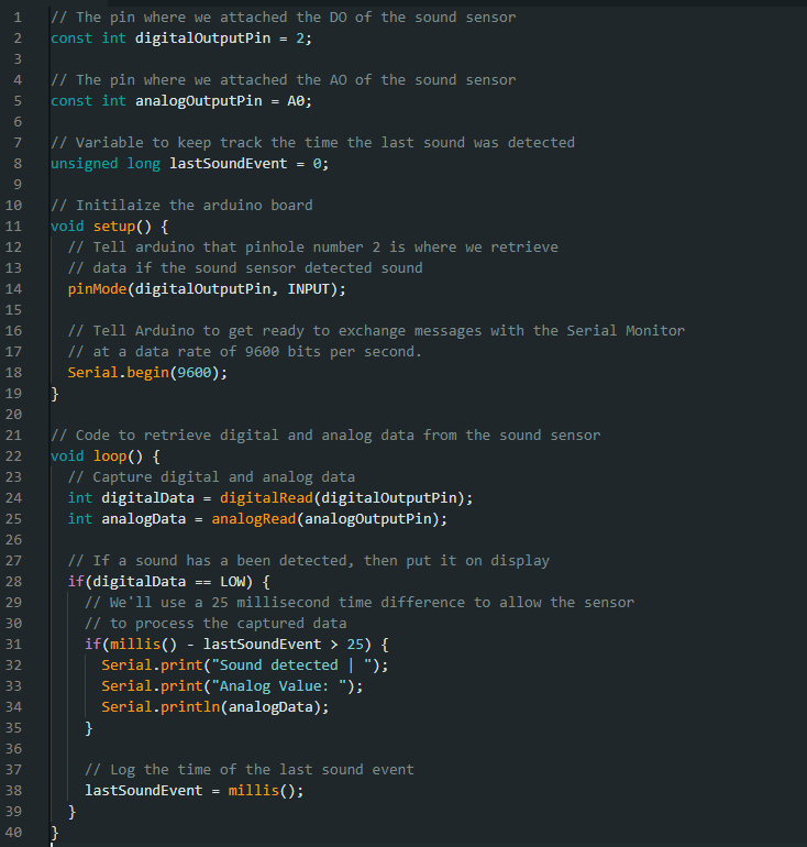
Once the code is verified and uploaded to the Arduino board, the Serial Monitor is expected to show an output if a sound is detected. The potentiometer on the sound sensor can be adjusted to modify its sensitivity to noise capture.