

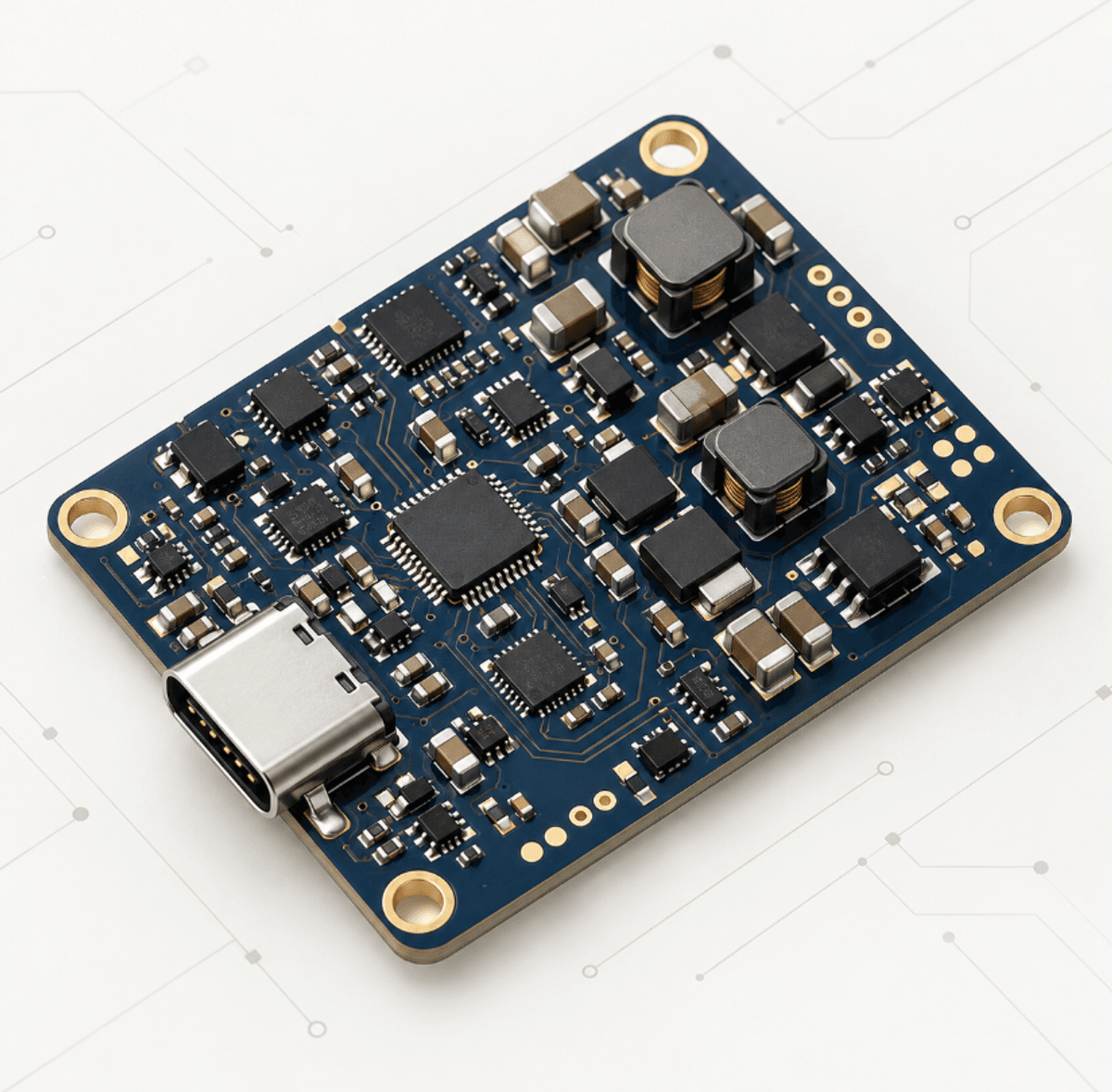
100W USB-C PD Battery Charger Module Plan
$680
# 100W USB-C PD Battery Charger PCB Design Files & Engineering Plan
## Develop High-Power USB-C Charging Hardware
Explore a structured engineering package for developing a compact 100W USB-C Power Delivery (PD) battery-charging module designed for portable electronics, battery-powered equipment, and power-management applications.
This digital engineering package provides a starting point for hardware teams working on USB-C power negotiation, bidirectional power flow, battery charging, and system power-path management. It is designed to help engineers evaluate the architecture, adapt the design to their application, and prepare for prototype development and manufacturing review.
The proposed architecture supports USB-C PD negotiation up to 20V/5A, a buck-boost charging stage for 1–4-cell battery configurations, and source/sink operating modes. The design concept also addresses protection, thermal management, and integration considerations for compact electronic products.
Whether you're developing a portable power station, a high-capacity power bank, a smart speaker, or specialized field equipment, this package provides engineering documentation to support your product-development process.
## What's Included
Your digital engineering package includes the following resources:
**1. System Requirements & Power-Flow Diagram**
A functional overview of the intended charging system, operating modes, and primary power paths.
**2. Annotated Circuit Schematic**
Engineering documentation covering USB-C Power Delivery negotiation, charging control, protection architecture, and system power-path management.
**3. Editable Schematic & PCB Source Files**
Design resources intended for technical review, adaptation, and further development.
**4. PCB Fabrication Package**
Gerber files, drill data, stack-up information, and fabrication notes for manufacturing assessment.
**5. Bill of Materials (BOM)**
A component list with sourcing guidance and practical alternatives to support procurement planning.
**6. Assembly & Connector Documentation**
Assembly drawings, component placement references, and connector definitions to assist with PCB assembly planning.
**7. Configuration Guide**
Reference guidance for charging limits, battery profiles, and power-source or power-sink operating modes.
**8. Hardware Bring-Up & Validation Checklist**
A structured starting point for evaluating initial hardware operation and planning electrical validation tests.
**9. Thermal, Battery-Safety & EMC Review Notes**
Engineering considerations for thermal performance, battery integration, electromagnetic compatibility, and enclosure design.
**10. Design-for-Manufacturing (DFM) Handoff Brief**
Documentation to help prepare for prototype costing, manufacturing discussions, and volume-production planning.
## Technical Architecture
**USB-C Power Delivery:** Negotiated input architecture supporting up to 20V at 5A, subject to compatible equipment and protocol implementation.
**Power Rating:** Up to 100W at the specified 20V/5A input operating point. Actual output power depends on conversion losses, component ratings, thermal conditions, and the final implementation.
**Battery Configurations:** Intended for 1–4-cell battery systems, with final supported chemistry, voltage limits, and charging profiles requiring verification.
**Power Conversion:** Buck-boost charging architecture designed to accommodate differing input and battery voltages.
**Power Roles:** Source and sink operating modes for applications requiring configurable power flow.
**System Coordination:** I²C-based controller-to-charger coordination within the proposed architecture.
**Protection & Integration:** Design considerations for surge protection, system power-path management, thermal behavior, and battery safety.
## Potential Applications
This engineering package may be useful for teams developing:
- High-capacity USB-C power banks.
- Portable power stations and backup-power equipment.
- Battery-powered field electronics.
- Smart speakers and portable audio products.
- Embedded electronics requiring USB-C charging.
- Custom battery-charging and power-management modules.
- Commercial electronic products requiring tailored charging hardware.
The package is intended for technically experienced buyers who can review circuit designs, work with PCB design tools, and validate battery-powered electronics.
## From Engineering Files to Manufacturing
### Step 1: Evaluate the Design
Review the system architecture, circuit schematic, power-flow strategy, component selection, and PCB documentation before committing to a hardware build.
### Step 2: Adapt the Requirements
Adjust the design requirements for your target battery configuration, charging limits, connector arrangement, power roles, enclosure dimensions, and thermal constraints.
### Step 3: Validate the Hardware
Develop and test a prototype to verify power negotiation, charging behavior, conversion efficiency, protection functionality, thermal performance, and battery compatibility.
### Step 4: Prepare for Production
Use the manufacturing documentation as a starting point for fabrication quotations, assembly planning, design-for-manufacturing review, and supplier discussions.
For teams pursuing commercial production, additional engineering review, prototype assembly, compliance planning, and volume-manufacturing support can be discussed separately.
## Who Should Purchase This Package?
This digital engineering resource is intended for:
- Hardware engineers and PCB designers.
- Electronics startups developing power products.
- Product-development teams working on battery-powered devices.
- Embedded systems developers.
- Electronics manufacturers evaluating custom charging hardware.
- Engineering teams preparing a concept for prototyping and production assessment.
A working knowledge of USB-C Power Delivery, switching power converters, rechargeable battery systems, PCB design, and electrical testing is recommended.
## Important Technical & Safety Information
This is a digital engineering package, not a physical charger or assembled electronic module. Batteries, components, prototype boards, enclosure hardware, certification, and manufacturing services are not included in the purchase unless separately agreed upon.
The documentation is intended to support engineering evaluation and product development. The stated power levels and battery configurations describe the intended architecture and must not be interpreted as proof of validated performance or production readiness.
Before building or commercializing a device, the final design must undergo appropriate electrical verification, USB-C PD protocol testing, battery charging and protection validation, thermal testing, EMC assessment, and applicable regulatory and product-safety evaluations.
High-power charging systems can create serious hazards if improperly designed or assembled. Battery chemistry, cell configuration, charging voltage, current limits, component ratings, cooling, and fault protection must be verified by qualified personnel.
The final implementation may require component substitutions, additional engineering, PCB revisions, and prototype testing.
## Digital Delivery
This is a downloadable digital product. No physical product will be shipped.
After purchase, access the supplied engineering files and documentation through the delivery method specified on the product checkout page.
## Take Your Power Electronics Project Further
Get a structured starting point for evaluating and developing a high-power USB-C charging solution. Use the engineering resources to assess the proposed architecture, adapt your product requirements, and prepare for the next stages of prototype development and manufacturing.
**Purchase the 100W USB-C PD Battery Charger Engineering Package to access the digital design resources.**
$680
Enter a fair price
$
$680