

Introducing the L298N Motor Driver
We’re going to use the L298N motor driver that can handle up to 3A at 35V. Additionally, it allows us to drive two DC motors simultaneously, which is perfect for building a robot.
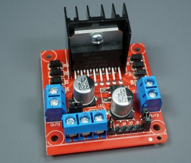
L298N Motor Driver pinout
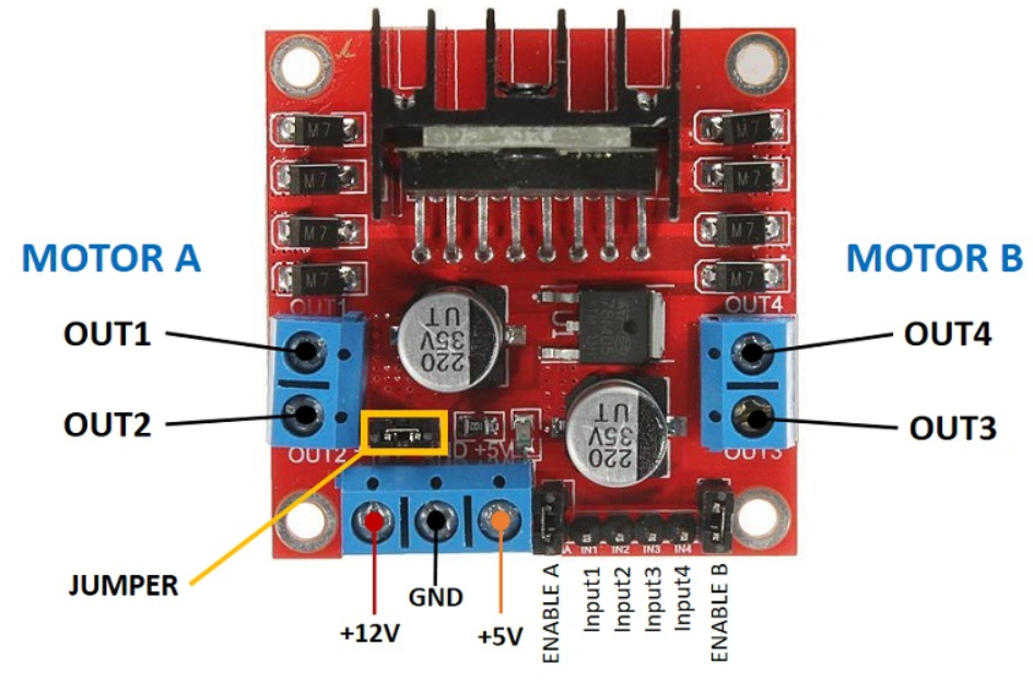
The motor driver has a two-terminal block on each side for each motor. OUT1 and OUT2 at the left and OUT3 and OUT4 at the right.
OUT1: DC motor A + terminal
OUT2: DC motor A – terminal
OUT3: DC motor B + terminal
OUT4: DC motor B – terminal
At the bottom, you have a three-terminal block with +12V, GND, and +5V. The +12V terminal block is used to power up the motors. The +5V terminal is used to power up the L298N chip. However, if the jumper is in place, the chip is powered using the motor’s power supply and you don’t need to supply 5V through the +5V terminal.
Important: despite the +12V terminal name, you can supply any voltage between 5V and 35V (but 6V to 12V is the recommended range).
Note: if you supply more than 12V, you need to remove the jumper and supply 5V to the +5V terminal.
+12V: The +12V terminal is where you should connect the motor’s power supply
GND: power supply GND
+5V: provide 5V if jumper is removed. Acts as a 5V output if jumper is in place
Jumper: jumper in place – uses the motor power supply to power up the chip. Jumper removed: you need to provide 5V to the +5V terminal. If you supply more than 12V, you should remove the jumper
At the bottom right you have four input pins and two enable terminals. The input pins are used to control the direction of your DC motors, and the enable pins are used to control the speed of each motor.
IN1: Input 1 for Motor A
IN2: Input 2 for Motor A
IN3: Input 1 for Motor B
IN4: Input 2 for Motor B
EN1: Enable pin for Motor A
EN2: Enable pin for Motor B
There are jumper caps on the enable pins by default. You need to remove those jumper caps to control the speed of your motors. Otherwise, they will either be stopped or spinning at the maximum speed.
Connection Diagram
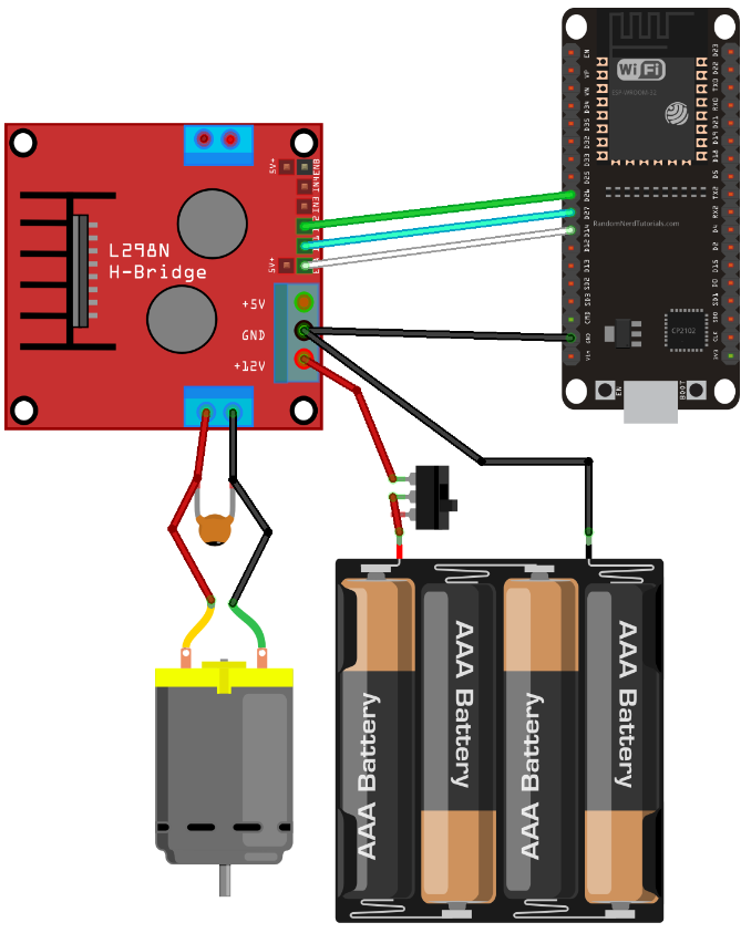
Powering the LN298N Motor Driver
The DC motor requires a big jump in current to move, so the motors should be powered using an external power source from the ESP32. As an example, we’re using 4AA batteries, but you can use any other suitable power supply. In this configuration, you can use a power supply with 6V to 12V.
The switch between the battery holder and the motor driver is optional, but it is very handy to cut and apply power. This way you don’t need to constantly connect and then disconnect the wires to save power.
We recommend soldering a 0.1uF ceramic capacitor to the positive and negative terminals of the DC motor, as shown in the diagram to help smooth out any voltage spikes. (Note: the motors also work without the capacitor.)
Code: ESP32 with a DC Motor – Control Speed and Direction
// Motor A
int motor1Pin1 = 27;
int motor1Pin2 = 26;
int enable1Pin = 14;

// Setting PWM properties
const int freq = 30000;
const int pwmChannel = 0;
const int resolution = 8;
int dutyCycle = 200;

void setup() {
  // sets the pins as outputs:
  pinMode(motor1Pin1, OUTPUT);
  pinMode(motor1Pin2, OUTPUT);
  pinMode(enable1Pin, OUTPUT);

  // configure LEDC PWM
  ledcAttachChannel(enable1Pin, freq, resolution, pwmChannel);

  Serial.begin(115200);

  // testing
  Serial.print("Testing DC Motor...");
}

void loop() {
  // Move the DC motor forward at maximum speed
  Serial.println("Moving Forward");
  digitalWrite(motor1Pin1, LOW);
  digitalWrite(motor1Pin2, HIGH);
  delay(2000);

  // Stop the DC motor
  Serial.println("Motor stopped");
  digitalWrite(motor1Pin1, LOW);
  digitalWrite(motor1Pin2, LOW);
  delay(1000);

  // Move DC motor backwards at maximum speed
  Serial.println("Moving Backwards");
  digitalWrite(motor1Pin1, HIGH);
  digitalWrite(motor1Pin2, LOW);
  delay(2000);

  // Stop the DC motor
  Serial.println("Motor stopped");
  digitalWrite(motor1Pin1, LOW);
  digitalWrite(motor1Pin2, LOW);
  delay(1000);

  // Move DC motor forward with increasing speed
  digitalWrite(motor1Pin1, HIGH);
  digitalWrite(motor1Pin2, LOW);
  while (dutyCycle <= 255){
    ledcWrite(enable1Pin, dutyCycle);
    Serial.print("Forward with duty cycle: ");
    Serial.println(dutyCycle);
    dutyCycle = dutyCycle + 5;
    delay(500);
  }
  dutyCycle = 200;
}
All the best.