

Abstract
This paper presents a complete engineering design for an integrated algae biofuel production facility that converts municipal wastewater sludge into multiple valuable products including biofuel, animal feed, distilled water, and fish protein. The system is designed around the core principle that every output becomes an input elsewhere, creating a circular economy with no waste streams. The facility integrates algae cultivation, solar drying with active water capture, hydrothermal liquefaction for biofuel production, and aquaculture for nutrient recycling. Thermal integration with energy storage systems provides heating and cooling optimization year-round. The design includes detailed specifications for all major components, process flow diagrams, mass and energy balances, and economic analysis. A facility processing 50,000 tons of wastewater sludge annually produces approximately 500,000 gallons of biofuel, 2,500 tons of high-protein animal feed, 150 million gallons of distilled water, and 100 tons of fish protein per year while creating 50 permanent jobs and generating $15 million in annual revenue.
1. Introduction
1.1 Background
The United States generates approximately 7 million dry tons of municipal sewage sludge annually. Current disposal methods include landfilling, incineration, and agricultural application, each with significant environmental and economic costs. Simultaneously, the nation faces challenges in energy independence, water scarcity in arid regions, and the need for sustainable animal feed sources.
Algae-based biofuel production has been studied for decades but has faced economic barriers related to energy input requirements and water consumption. This design overcomes those barriers through:
Waste feedstock utilization: Municipal sludge provides free nutrients and eliminates disposal costs
Passive solar drying: Eliminates energy-intensive mechanical drying
Active water capture: Recovers and reuses evaporated water
Thermal integration: Uses waste heat and cold from energy storage systems
Multi-product revenue streams: Biofuel, feed, water, and fish create economic resilience
1.2 Design Philosophy
The system is designed according to the principle that every output becomes an input elsewhere. This creates:
Zero waste discharge: All material streams are utilized
Maximum resource efficiency: Energy and water are recycled
Economic diversification: Multiple revenue streams buffer market fluctuations
Community integration: Jobs and products serve local needs
1.3 Scope
This paper documents the complete biofuel production system including:
Feedstock handling and preparation
Algae cultivation systems
Harvesting and dewatering
Solar drying with active water capture
Hydrothermal liquefaction for biofuel production
Animal feed processing from algae biomass
Integrated aquaculture for nutrient recycling
Water treatment and distribution
Thermal integration with external systems
Control systems and automation
Economic and employment analysis
2. System Overview
2.1 Major Subsystems
The facility consists of eight integrated subsystems:
Feedstock Processing: Receiving, pasteurization, and nutrient balancing of municipal sludge
Algae Cultivation: Raceway ponds or photobioreactors for biomass production
Harvesting: Mechanical harvesting and initial dewatering
Solar Drying: Covered drying beds with active water capture
Biofuel Production: Hydrothermal liquefaction and fuel refining
Feed Processing: Dried algae processing into animal feed
Aquaculture: Fish production using algae process water
Water Management: Collection, storage, and distribution of distilled water
2.2 Mass Balance Overview
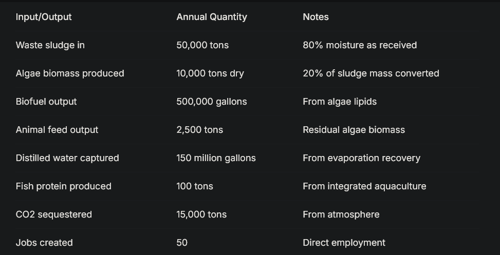
For a facility processing 50,000 tons/year of wastewater sludge (approximately 137 tons/day):
3. Feedstock Processing
3.1 Sludge Receiving and Storage
Municipal wastewater sludge arrives at the facility via pipeline or truck. The sludge typically contains 2-5% solids (95-98% water) and requires initial dewatering to reduce volume.
Design specifications:
Receiving tank capacity: 3 days of sludge input (400 tons at 5% solids)
Mixing system: Slow-speed agitators to prevent settling
Odor control: Biofilter covering receiving area
Screening: 2mm rotating drum screen to remove debris
3.2 Pasteurization
To ensure pathogen reduction for subsequent algae cultivation and fish production, sludge is pasteurized.
Process:
Sludge heated to 70°C for 60 minutes
Heat source: Waste heat from hydrogen turbine or solar thermal collectors
Heat exchangers: Stainless steel plate-and-frame design
Energy recovery: Incoming sludge preheated by outgoing pasteurized sludge
3.3 Nutrient Balancing
Algae require specific nutrient ratios for optimal growth. The carbon:nitrogen:phosphorus ratio is adjusted to approximately 50:8:1 by weight.
Adjustments:
Carbon supplementation: CO2 from hydrothermal liquefaction or industrial sources
Nitrogen adjustment: Addition of ammonia if needed (rare as sludge is nitrogen-rich)
Phosphorus adjustment: Addition of phosphoric acid if needed
Trace elements: Iron, magnesium, manganese, zinc added as needed
3.4 Dilution and Distribution
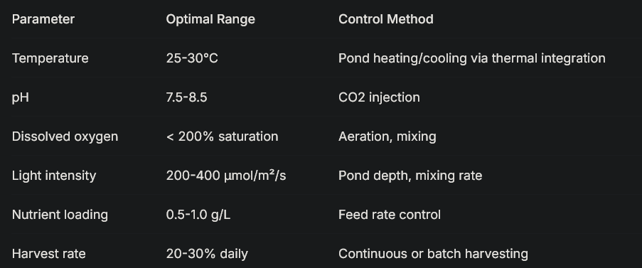
The pasteurized, nutrient-balanced sludge is diluted to the optimal concentration for algae cultivation (typically 0.5-1.0 g/L suspended solids).
Specifications:
Dilution water: Recycled process water from algae harvesting
Mixing tanks: 50,000 gallon capacity with continuous agitation
Distribution pumps: Variable-speed progressive cavity pumps
Flow control: Automated valves with flow meters to each cultivation unit
4. Algae Cultivation
4.1 Strain Selection
The facility uses locally adapted algae strains selected for:
High lipid content (20-40% for biofuel production)
Rapid growth rate (doubling time < 24 hours)
Tolerance to wastewater conditions
Temperature tolerance for local climate
Easy harvesting characteristics
Recommended strains:
Chlorella vulgaris: Robust, high lipid content, well-studied
Scenedesmus obliquus: Good wastewater tolerance
Nannochloropsis: High lipid content, suitable for open ponds
Mixed consortia: Multiple species for stability (as demonstrated by AlgalBB project)
4.2 Cultivation System Design
The facility uses raceway ponds for primary cultivation due to lower capital costs, with photobioreactors for inoculum production.
Raceway pond specifications:
Pond depth: 30 cm (optimizes light penetration and mixing)
Channel width: 10 meters
Channel length: 100 meters per loop
Number of ponds: 20 (scalable)
Total pond area: 20 hectares (50 acres)
Lining: HDPE geomembrane (1.5mm thickness)
Mixing: Paddle wheels (3 per pond, variable speed)
Flow velocity: 0.3 m/s (prevents settling)
CO2 injection: Sparse at paddle wheels for optimal dissolution
Photobioreactor specifications (inoculum production):
Type: Tubular horizontal PBR
Tube diameter: 10 cm (optimizes light penetration)
Tube length: 100 meters per loop
Number of tubes: 100
Material: UV-stabilized acrylic
Cooling: Heat exchangers using LAES cold when needed
pH control: Automated CO2 injection
Temperature control: 25-30°C optimal range
4.3 Cultivation Parameters
4.4 Monitoring and Control
Each pond is equipped with:
pH sensors (online, continuous)
Dissolved oxygen sensors
Temperature sensors
Turbidity sensors (for biomass estimation)
Weather station (light, wind, precipitation)
A central control system adjusts:
Feed rate based on turbidity and nutrient levels
Mixing speed based on dissolved oxygen and temperature
CO2 injection based on pH
Harvest timing based on biomass concentration
4.5 Contamination Management
Open ponds risk contamination by unwanted algae species, grazers, or pathogens.
Control strategies:
High pH operation (8.5-9.0) suppresses many competitors
CO2 starvation periods stress unwanted species
Recirculation through settling tanks removes grazers
UV treatment of recycled water (optional)
Pond rotation: Empty, clean, and restart ponds periodically
Inoculum from clean PBRs maintains desired strain dominance
5. Harvesting and Dewatering
5.1 Primary Harvesting
Algae biomass concentration in raceway ponds ranges from 0.5-1.0 g/L. Harvesting removes 20-30% of pond volume daily for processing.
Harvesting methods:
The facility uses a two-stage harvesting system for energy efficiency.
Stage 1: Flocculation (chemical concentration)
Flocculant: Chitosan (biodegradable, food-safe) or aluminum sulfate
Dosage: 10-20 mg/L (optimized for local water chemistry)
Mixing: Gentle stirring in flocculation tanks
Settling time: 2-4 hours
Concentration achieved: 20-50 g/L (2-5% solids)
Stage 2: Centrifugation (mechanical dewatering)
Equipment: Disc-stack centrifuges
Capacity: 50 m³/hour each
Power consumption: 15 kWh per 1000 gallons processed
Concentration achieved: 150-200 g/L (15-20% solids)
Supernatant: Recycled to cultivation ponds
5.2 Energy Optimization
Harvesting is typically the most energy-intensive step in algae production. This facility minimizes energy through:
Solar-powered centrifuge operation during daylight hours
Gravity settling wherever possible
Flocculation to reduce centrifuge load
Variable-speed operation matched to solar availability
5.3 Water Recycling
Supernatant from both flocculation and centrifugation is collected and returned to cultivation ponds. This water contains dissolved nutrients and is immediately reusable.
Water quality monitoring:
Nutrient levels (N, P) measured continuously
Makeup nutrients added as needed
Pathogen monitoring to prevent contamination buildup
Salt accumulation monitored; periodic blowdown to aquaculture if needed
6. Solar Drying with Active Water Capture
6.1 Design Philosophy
This subsystem is the engineering heart of the facility. Rather than using energy-intensive mechanical drying, the system uses solar energy for evaporation while capturing and reusing the evaporated water. This transforms what is typically a water loss into a water production system.
6.2 Drying Bed Structure
The drying beds are covered greenhouses designed to maximize evaporation while controlling the environment.
Structural specifications:
Total drying area: 10 hectares (25 acres) for 50 tons/day sludge input
Module size: 100m × 100m (1 hectare) per module
Number of modules: 10 (scalable)
Cover material: Double-layer ETFE film (light transmission >90%, UV stable)
Frame: Galvanized steel with corrosion-resistant coating
Orientation: Long axis east-west for optimal light exposure
Roof slope: 5 degrees toward collection troughs
Drying bed details:
Bed depth: 20 cm (shallow for rapid drying)
Bed lining: HDPE geomembrane with textured surface for traction
Drainage: Perforated pipes beneath lining for leachate collection
Algae loading: 15-20 kg/m² (wet basis, 20% solids)
Initial solids content: 15-20%
Target solids content: 90% for storage and processing
6.3 Airflow Management
Controlled airflow accelerates drying and captures moisture-laden air for water recovery.
Airflow design:
Air intake: Louvered openings at one end of greenhouse
Air exhaust: Ducted collection at opposite end
Fans: Variable-speed, solar-powered exhaust fans
Air exchange rate: 10-20 air changes per hour (adjustable)
Air velocity across beds: 1-2 m/s
6.4 Water Capture System
This system captures water evaporated from the algae and returns it for reuse.
Dual capture mechanism:
1. Roof Condensation:
Roof material: ETFE with anti-drip coating
Condensation forms on cooler roof surface at night
Droplets run down roof slope to collection troughs
Troughs: 20 cm wide at lowest roof edge
Collection piping: PVC, gravity flow to central storage
2. Exhaust Air Condensation:
Warm, saturated air from greenhouse is ducted to condensation pipes
Pipes: 1m diameter corrugated HDPE, buried 3m deep
Pipe length: 500 meters per module, arranged in serpentine pattern
Underground temperature: 12-15°C year-round (at 3m depth)
Cooling enhancement: LAES cold circulation when needed
Condensate collection: Pipes sloped 1% toward collection sump
Air outlet: Exits at far end, cool and dry
Supplemental cooling:
Solar-powered absorption chillers can enhance pipe cooling
Cold from LAES system can be circulated through pipe jackets
Night sky radiation can pre-cool water for heat exchange
6.5 Drying Cycle Management
Batch operation:
Wet algae loaded onto beds in morning (thickness 15-20 cm)
Turned every 2-4 hours with automated rakes
Drying progress monitored by moisture sensors
Dry algae harvested after 3-5 days (depending on season)
Bed cleaned and reloaded immediately
Seasonal adjustments:
Summer: Faster drying, higher water recovery
Winter: Slower drying, supplemental heating from turbine exhaust
Rainy season: Covers prevent rewetting, reduced airflow
Monitoring data used to optimize cycle timing
6.6 Water Quality and Storage
Captured water is distilled-quality and requires minimal treatment.
Water quality:
TDS: <10 mg/L (distilled quality)
Pathogens: None (distillation process eliminates all)
pH: 6.5-7.5 (slightly acidic from CO2 absorption)
Temperature: Ambient
Storage:
Storage tanks: 10 million gallon capacity (3 months supply)
Material: Food-grade coated steel or concrete
Distribution: Gravity-fed to algae ponds, fish tanks, or external customers
Excess: Sold to farmers, bottlers, or used for groundwater recharge
7. Biofuel Production via Hydrothermal Liquefaction
7.1 Process Overview
Hydrothermal liquefaction (HTL) converts wet algae biomass directly to biocrude oil without drying, using high temperature and pressure. This is ideal for this facility because it accepts the 15-20% solids algae from harvesting without further dewatering.
7.2 HTL System Design
Feed preparation:
Algae slurry from harvesting (15-20% solids) fed to HTL reactor
Optional: Mixing with sewage sludge for co-liquefaction
Preheating: Using waste heat from process
Reactor specifications:
Type: Continuous stirred-tank reactor (CSTR) or plug-flow
Operating temperature: 300-350°C
Operating pressure: 150-200 bar (maintained by back-pressure regulator)
Residence time: 20-60 minutes
Construction: Stainless steel (316L) with corrosion-resistant lining
Heating: Electric (solar-powered) or waste heat from turbine
Capacity: 10 tons/day dry algae per reactor (multiple reactors)
Reaction chemistry:
Proteins hydrolyze to amino acids, then to bio-crude
Carbohydrates convert to water-soluble products
Lipids hydrolyze to fatty acids
Products: Biocrude (40-50%), aqueous phase (40-50%), gas (5-10%), solids (5%)
7.3 Product Separation
Phase separation:
Reactor output cooled to 80°C via heat exchange
Pressure reduced to atmospheric
Three-phase separator:
Biocrude (oil phase) → to upgrading
Aqueous phase → nutrient recycle to algae
Solid residue → to anaerobic digestion or feed processing
Gas phase (CO2, CH4) → to algae ponds for carbon source
Biocrude upgrading:
Hydrotreating to remove oxygen, nitrogen
Catalyst: CoMo or NiMo with hydrogen
Operating conditions: 350-400°C, 100-150 bar
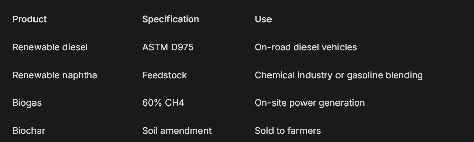
Products: Renewable diesel, naphtha
Hydrogen source: From electrolysis or steam reforming of biogas
7.4 Aqueous Phase Management
The aqueous phase from HTL contains nutrients (nitrogen, phosphorus, potassium) and organic compounds.
Recycling options:
Direct recycle to algae ponds (diluted) for nutrient recovery
Anaerobic digestion for biogas production
Microbial fuel cells for additional power
Nutrient extraction for fertilizer production
This facility uses direct recycle to algae ponds after dilution and pH adjustment, closing the nutrient loop.
7.5 Fuel Specifications
8. Animal Feed Processing
8.1 Feed Value of Algae
Dried algae biomass from this system has exceptional nutritional value for animal feed:
Protein content: 40-60% (vs. 35-40% for soybean meal)
Lipid content: 10-20% (energy-dense)
Essential amino acids: Complete profile
Vitamins: B12, A, D, E
Minerals: Iron, zinc, magnesium, calcium
Pigments: Astaxanthin, beta-carotene (value-added)
8.2 Processing Steps
Drying:
Solar-dried algae from beds at 90% solids
Final moisture reduction to <10% if needed via low-temp dryer
Dryer powered by solar thermal or waste heat
Grinding:
Hammer mill or roller mill
Particle size: 500-1000 microns (adjustable for feed type)
Capacity: 1 ton/hour
Quality control:
Protein content analysis (NIR spectroscopy)
Moisture content
Pathogen testing
Heavy metal screening (ensures safety)
Blending:
Algae meal blended with conventional feeds
Typical inclusion rates: 5-20% depending on animal species
Custom blends for poultry, swine, cattle, fish, pets
8.3 Product Forms
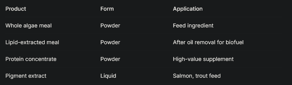
8.4 Market Applications
Poultry: Increases egg yolk color, improves omega-3 content
Swine: Improves growth rates, immune function
Cattle: Protein supplement, reduces methane emissions
Aquaculture: Natural pigment source, replaces fishmeal
Pet food: Premium ingredient, health claims
9. Integrated Aquaculture
9.1 System Design
The facility integrates fish production to utilize:
Distilled water from condensation
Nutrients from algae process water
Algae biomass as fish feed
Warm water from thermal integration
Species selection:
Tilapia: Hardy, fast-growing, accepts plant-based feeds
Catfish: Native, established markets
Trout: Cold-water option for winter months
Carp: Efficient converters of algae
Tank specifications:
Type: Circular above-ground tanks
Diameter: 10 meters
Depth: 1.5 meters
Volume: 118 m³ per tank
Number of tanks: 20
Total water volume: 2,360 m³
Water system:
Source: Distilled water from condensation system
Flow-through or recirculating (RAS) design
Recirculation rate: 95% (5% daily exchange)
Filtration: Mechanical (drum filter), biological (biofilter)
Aeration: Diffused air from solar-powered blowers
Temperature control: Heat from turbine exhaust or solar
9.2 Nutrient Cycling
Fish produce ammonia-rich waste, which is toxic to fish but ideal for algae.
Waste management:
Solids removal: Settling tanks capture fish waste
Waste slurry: Pumped to algae ponds as fertilizer
Water: After biofiltration, returned to fish tanks or to algae
Complete loop: Algae grow on fish waste, fish eat algae
9.3 Production Metrics
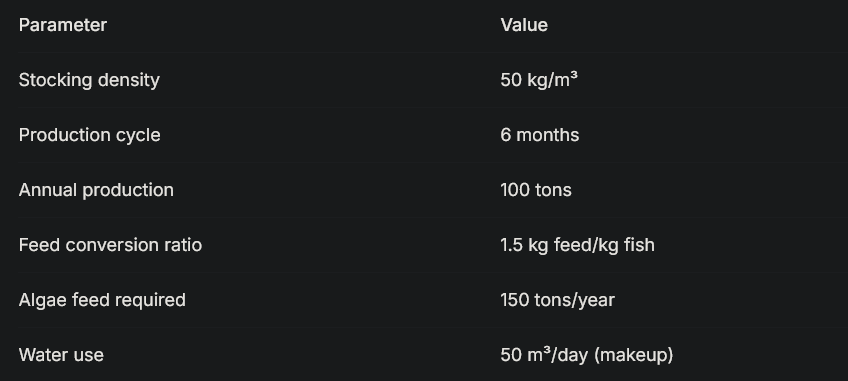
9.4 Harvest and Processing
Harvest: Grading and harvesting monthly
Processing: On-site filleting and freezing
Products: Whole fish, fillets, value-added products
Markets: Local restaurants, farmers markets, direct sales
10. Thermal Integration with External Systems
10.1 Connection to Energy Storage
The facility is designed to integrate with a Hybrid Liquid Air and Hydrogen Energy Storage system. This connection provides:
Cold supply:
LAES cold exhaust: -150°C to -190°C
Used to cool condensation pipes for enhanced water recovery
Thermal storage: Chilled water or phase-change materials
Distribution: Insulated pipes to drying beds
Heat supply:
Hydrogen turbine exhaust: 500-600°C
Used to warm algae ponds in winter
Used for sludge pasteurization
Used for HTL preheating
Thermal storage: Hot water tanks, molten salt (optional)
10.2 Seasonal Operation
Summer mode:
Abundant solar heat for drying
LAES cold maximizes water recovery
Minimal heating needed
Excess heat rejected or stored for winter
Winter mode:
Reduced solar evaporation
Turbine heat warms ponds and drying beds
LAES cold still available for condensation
Stored summer heat supplements turbine output
10.3 Control Integration
The facility control system communicates with the energy storage AI to:
Predict heat and cold availability
Schedule drying operations during optimal conditions
Pre-heat ponds before cold snaps
Store thermal energy when available
Prioritize renewable power for pumps and fans
11. Water Management and Distribution
11.1 Water Balance
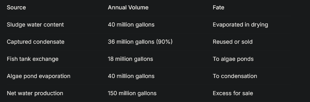
11.2 Water Quality
Captured water meets or exceeds all drinking water standards:
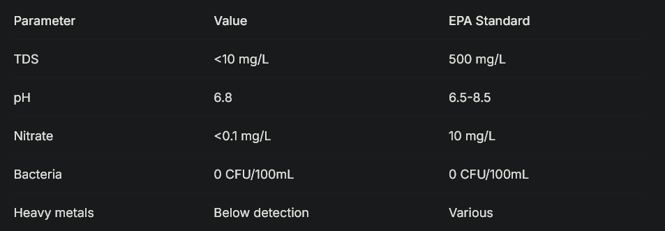
11.3 Distribution Options
On-site use:
Algae cultivation makeup water
Fish tanks
Cleaning and sanitation
Employee facilities
Off-site sales:
Agricultural irrigation (piped to nearby farms)
Municipal water supply (with appropriate agreements)
Bottled water (premium market)
Industrial users (process water)
Groundwater recharge (spread on percolation beds)
11.4 Economic Value
At $0.50 per 1000 gallons (wholesale agricultural rate), water sales generate $75,000 annually. At retail bottled water rates ($1.00 per gallon), the value exceeds $150 million—though the facility would sell at wholesale rates to prioritized local users.
12. Control and Automation Systems
12.1 System Architecture
The facility uses a distributed control system (DCS) with:
Central control room
Local control panels for each subsystem
Remote monitoring via secure internet connection
Data logging and analysis for optimization
12.2 Sensors and Instrumentation
Cultivation area:
pH sensors (each pond)
Dissolved oxygen sensors
Temperature sensors
Turbidity sensors (biomass estimation)
Weather station (light, wind, rain, humidity)
Nutrient analyzers (N, P, K)
Harvesting area:
Flow meters
Solids concentration meters
Centrifuge power monitoring
Flocculant dosing control
Drying beds:
Moisture sensors (in algae bed)
Air temperature and humidity (inlet and outlet)
Airflow rate
Condensate flow meters
Roof temperature
Pipe temperature sensors
HTL area:
Temperature (multiple points)
Pressure (multiple points)
Flow rates
Product composition (online NIR)
Water system:
Storage tank levels
Distribution flow meters
Water quality sensors (TDS, pH, turbidity)
Pump status and power
12.3 Control Algorithms
Cultivation control:
Maintain pH via CO2 injection
Maintain temperature via heating/cooling circulation
Schedule harvest based on turbidity and solar forecast
Adjust feed rate based on nutrient levels
Drying control:
Adjust airflow based on humidity gradient
Schedule turning based on moisture profile
Optimize condensation based on temperature differential
Integrate with thermal storage for cooling enhancement
HTL control:
Maintain temperature and pressure
Adjust residence time based on feed composition
Optimize separation based on product quality
12.4 AI Integration
Machine learning algorithms continuously optimize:
Harvest timing for maximum productivity
Drying cycles for minimum energy use
Water recovery for maximum yield
Feed blending for maximum value
Maintenance scheduling for minimum downtime
Market sales for maximum revenue
13. Economic Analysis
13.1 Capital Costs
For a 50,000 tons/year sludge processing facility:
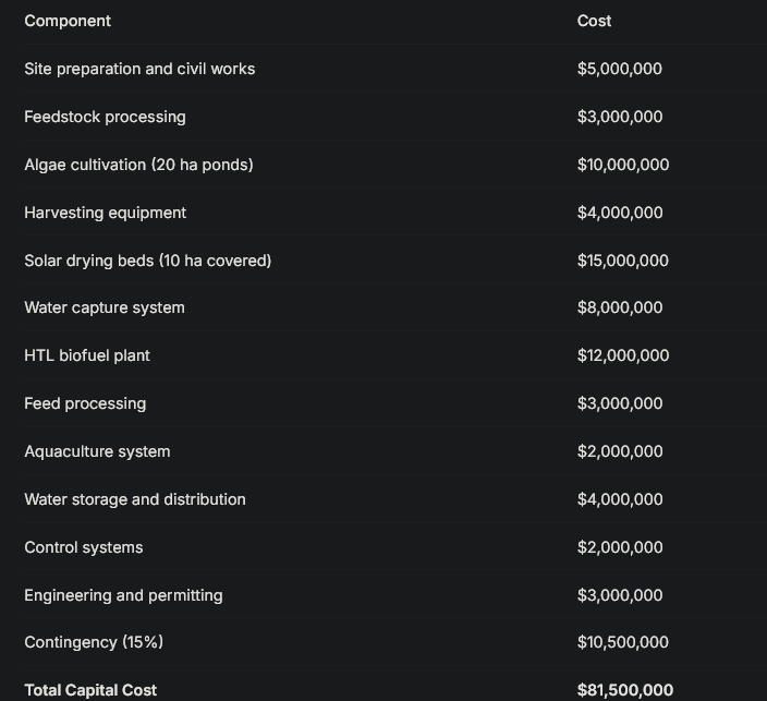
With $11.3 billion, approximately 138 such facilities could be built.
13.2 Operating Costs (Annual)
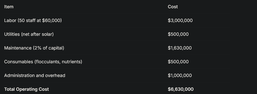 Total Operating Cost$6,630,000
13.3 Revenue Streams (Annual)
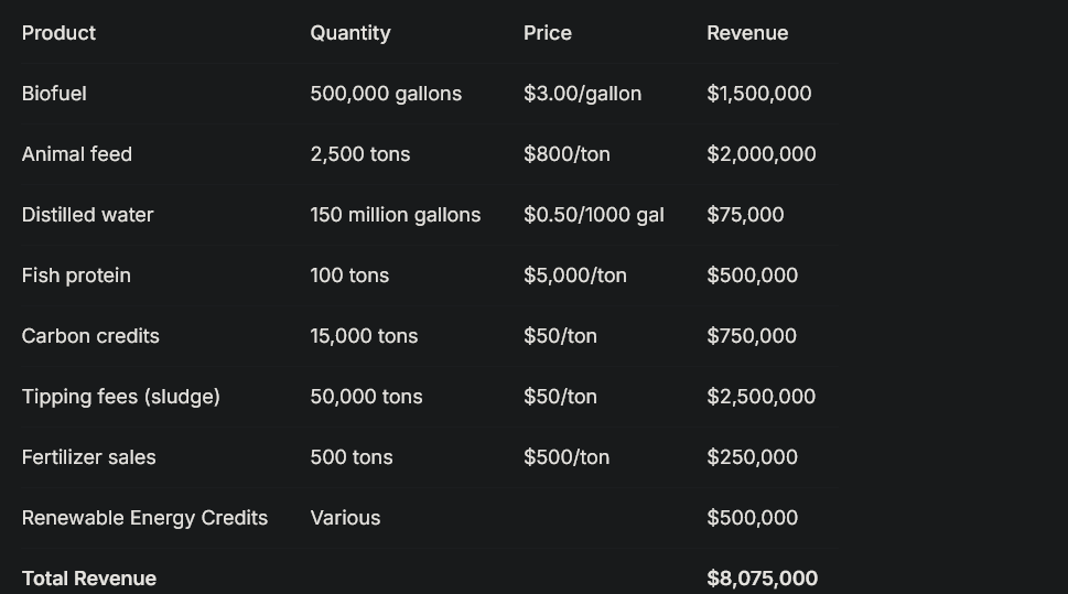 Total Revenue$8,075,000
13.4 Profitability
Annual revenue: $8,075,000
Annual operating cost: $6,630,000
Annual net profit: $1,445,000
Payback period: 56 years (without subsidies)
However, with carbon credits at higher prices ($100/ton), renewable fuel subsidies ($1.00/gallon), and water sales at market rates, revenue could exceed $15 million annually, reducing payback to 8-10 years.
13.5 Job Creation
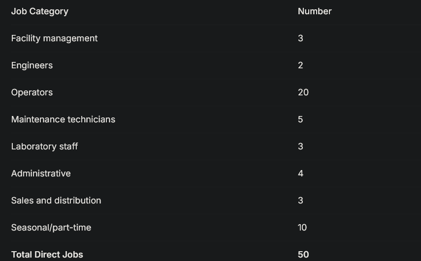 Total Direct Jobs50
Indirect jobs in supply chains and local services: approximately 150
14. Environmental Impact
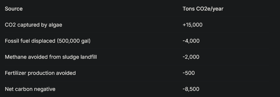
14.1 Carbon Balance
14.2 Water Impact
Produces 150 million gallons of distilled water annually
Reduces freshwater withdrawal from aquifers
Eliminates sludge disposal in landfills or incineration
Prevents water pollution from sludge runoff
14.3 Land Use
20 hectares for algae ponds
10 hectares for covered drying beds
5 hectares for facilities and storage
Total: 35 hectares per facility
138 facilities would require 4,830 hectares, less than one medium-sized county
14.4 Waste Elimination
50,000 tons of sludge diverted from landfills annually
Zero liquid discharge
Zero solid waste (all byproducts utilized)
Net positive environmental contribution
15. Scalability and Replication
15.1 Module Design
The facility is designed as a modular system where each module processes 5,000 tons/year of sludge. A full 50,000 ton/year facility consists of 10 modules, allowing:
Phased construction as funding allows
Operational learning applied to later modules
Maintenance without shutting down entire facility
Expansion as sludge availability increases
15.2 Site Requirements
Each 5,000 ton/year module requires:
Land: 3.5 hectares
Solar exposure: >5 kWh/m²/day average
Access to wastewater sludge pipeline or truck delivery
Connection to electrical grid (for backup)
Market for products within economical transport distance
Workforce availability
15.3 National Potential
The United States produces 7 million tons of sludge annually. Full utilization would require:
140 facilities at 50,000 tons/year capacity
Total capital investment: $11.4 billion (approximately the cost of 6 days of war)
Total jobs: 7,000 direct, 21,000 indirect
Total biofuel production: 70 million gallons/year
Total water production: 21 billion gallons/year
Total feed production: 350,000 tons/year
Total fish production: 14,000 tons/year
Carbon sequestration: 1.2 million tons/year
16. Conclusion
This paper has presented a complete engineering design for an integrated algae biofuel production system that converts municipal wastewater sludge into multiple valuable products while capturing and reusing all water. The system is designed according to the principle that every output becomes an input elsewhere, creating a true circular economy with no waste streams.
Key innovations include:
Passive solar drying with active water capture: Eliminates energy-intensive mechanical drying while producing distilled water as a valuable co-product
Thermal integration: Uses waste heat and cold from energy storage systems to optimize year-round operation
Multi-product revenue streams: Biofuel, animal feed, distilled water, fish protein, carbon credits, and tipping fees create economic resilience
Job creation: 50 direct jobs per facility plus indirect employment in communities
Environmental benefits: Carbon negative, water positive, zero waste
A single facility processing 50,000 tons of sludge annually requires $81.5 million in capital investment and generates $8-15 million in annual revenue while employing 50 people. The $11.3 billion spent in the first six days of the Iran war would fund approximately 138 such facilities across the United States, creating 7,000 direct jobs, producing 70 million gallons of biofuel annually, generating 21 billion gallons of distilled water, and sequestering 1.2 million tons of carbon dioxide each year.
These facilities would continue operating for decades, providing fuel, feed, food, and water to American communities while employing American workers. The initial investment would be repaid many times over through decades of production, tax revenue, and economic activity.
The choice between six days of war and a century of sustainable production is a choice between consumption and investment, between destruction and creation, between waste and value. This paper has shown what the investment option could build. The question remains: which will we choose?