

Beyond Silos – Connecting to Excellent Engineering
Chapter Three – Product Definition: The Compact Drive Unit
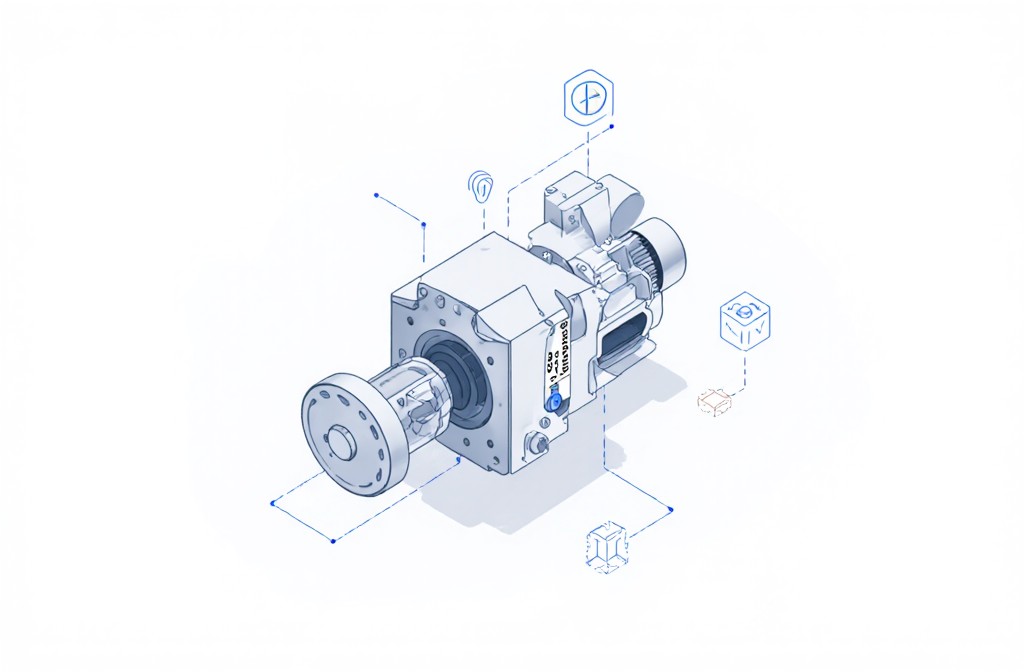 Every Systems Engineering process begins with one question: What exactly are we building?
Before diving into requirements, functions, or architectures, the foundation must be a shared understanding of the product itself — what it does, where its boundaries are, and how it fits into the overall system.
For this series, the chosen product is a Compact Drive Unit — a modular, self-contained drive system designed for flexible use in automation and assembly applications. It combines mechanical and electrical elements in a tightly integrated package and serves as a perfect case study for linking product and production system design.
From a Systems Engineering perspective, defining this product isn’t just an administrative step — it’s what makes traceability and consistency possible later on. By understanding its purpose, functions, and constraints, we create the foundation for every document, diagram, and model that will follow.
It also allows us to plan the assembly line holistically, integrating key aspects such as inline functional testing directly within the production process — ensuring that verification isn’t an afterthought, but a natural part of the system itself.
Functional Understanding – What Does a Compact Drive Unit Do?
At its core, a Compact Drive Unit converts electrical energy into controlled mechanical motion.
Its main functions can be described as follows:
Energy conversion – transforming electrical input into rotational output
Speed and torque control – maintaining precise motion profiles
Feedback and monitoring – providing real-time data on position, temperature, or load
Mechanical integration – coupling to the machine structure with defined interfaces
Thermal management – ensuring reliable operation under varying loads
In our case, we treat the control electronics as a black box.
We will not perform Systems Engineering on the internal control logic, firmware, or signal processing. Instead, we define what data is exchanged — the input and output behavior — so that we can focus on system-level integration and functional verification within the assembly environment.
This abstraction keeps the system manageable while still enabling realistic engineering decisions about interfaces, testing, and assembly constraints.
System Boundaries and Constraints
Every system operates within defined limits.
For our Compact Drive Unit, these include:
Mechanical boundaries – envelope size, mass, torque range
Electrical boundaries – supply voltage, power, and communication interface
Environmental conditions – operating temperature, vibration, and humidity
Integration boundaries – how the unit interacts with other systems, sensors, and test stations
By making these limits explicit, we can later connect them to assembly requirements, such as torque verification, part orientation, and quality control.
Why This Step Matters
Defining the product before jumping into models or diagrams ensures that everyone involved shares the same mental picture of the system.
In Document-Based Systems Engineering (DBSE), this description becomes the cornerstone of the Initial Phase — the reference point from which requirements, functions, and architecture evolve.
Without this shared foundation, even well-modeled systems risk inconsistencies.
With it, we can move forward systematically — knowing what the product is, what it must do, and how it will be tested.
Next Step
In the next post, coming Wednesday, we’ll translate this understanding into structured requirements and constraints, forming the backbone of our DBSE templates for the Initial Phase.
“Beyond Silos” is about more than MBSE.
It’s about rethinking how engineering teams connect —
and making that connection visible.