

Beyond Silos – Connecting to Excellent Engineering
After a longer break due to personal circumstances, I am back with new thoughts and experiences from the world of Systems Engineering.
The idea behind “Beyond Silos” remains the same: exploring how engineering teams can connect better, how information can flow between disciplines, and how structured approaches can help us build more reliable systems.
Over the past months, I continued working with these topics in practice — from requirements and project structures to interdisciplinary collaboration. I am looking forward to sharing these insights again.
Let’s continue making the connections between engineering disciplines visible.
Chapter Three Three – Product Definition: From Product to System
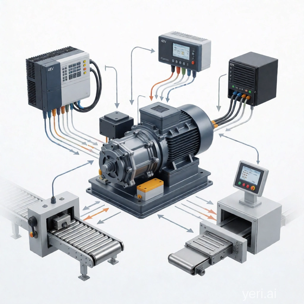
So far, we have looked at the Compact Drive Unit as an individual product.
We defined its purpose, described its main functions, and established preliminary technical parameters.
However, from a Systems Engineering perspective, a product never exists in isolation.
Every system interacts with its environment through defined interfaces, exchanges information, receives inputs, and produces outputs. Understanding these interactions is essential before moving into requirements, architecture, or detailed design.
Therefore, the next step in the product definition phase is to establish the system context.
1. Defining the System Boundary
A system boundary defines what belongs to the system under development and what is considered part of the surrounding environment.
In Systems Engineering terminology, this is the system of interest (SoI)
The following elements are outside the system boundary:
Conveyor mechanics
Higher-level control system (PLC)
Electrical power supply
Quality and traceability system
Operator interaction
Production environment
This does not mean that these elements are irrelevant. On the contrary — they define constraints and interfaces that the Drive Unit must satisfy.
The purpose of the system boundary is not to isolate the product, but to create a common understanding of where responsibilities begin and end.
2. External Interfaces
The Compact Drive Unit interacts with several external systems.
These interactions can be described without knowing the internal implementation details.
External Interfaces
Mechanical Interface – Conveyor System
Type: Mechanical
Direction: Interaction
Defines the physical connection between the Drive Unit and the conveyor system.
Includes mounting, alignment, and torque transmission.
Electrical Supply – Power System
Type: Energy
Direction: Input
Provides the required 48 V DC power supply for operation of the Drive Unit.
Communication Interface – PLC / Control System
Type: Data
Direction: Input / Output
Defines the exchange of control commands, status information, and feedback values between the Drive Unit and the higher-level control system.
Traceability Interface – Quality System
Type: Data
Direction: Output
Provides product identification data and test results for quality tracking and process documentation.
Human Interface – Operator
Type: Information
Direction: Input / Output
Defines information exchange with operators, including status indication, maintenance information, and service interactions.
At this stage, the focus is not on the internal design of the Drive Unit, but on the information and energy crossing the system boundary.
3. Input and Output Definition
A useful Systems Engineering approach is to describe the system through its inputs and outputs.
The Compact Drive Unit receives:
Electrical energy
Motion commands from the control system
Configuration parameters
Communication requests
The Compact Drive Unit provides:
Controlled mechanical motion
Position and status feedback
Diagnostic information
Measurement data from integrated sensors
These outputs represent the observable behavior of the system from an external perspective.
The internal processing of these signals remains outside the scope of this system definition.
Similar to the previous post, where the internal control electronics were treated as a black box, we focus on the externally visible behavior of the system.
This abstraction allows us to define interfaces and requirements without unnecessarily increasing complexity.
4. Why System Context Matters
Many engineering problems do not originate from individual components, but from missing connections between them.
Typical examples include:
Mechanical interfaces that are not compatible with surrounding systems
Communication requirements discovered too late
Missing test data needed for quality tracking
Unclear responsibility between engineering disciplines
By defining the system context early, these interactions become visible before detailed design begins.
This creates the foundation for traceability: requirements can be linked to interfaces, functions, and later verification activities.
The Next Step
With the Compact Drive Unit now defined from three perspectives — purpose, technical parameters, and system context — the product definition phase is complete.
The next step is to establish the structure that allows us to manage this information throughout the project.
In the next chapter, we will start the Initial Phase of Document-Based Systems Engineering by creating the Project Charter — the first document that defines project identity, responsibilities, and boundaries.
“Beyond Silos” is about more than MBSE.
It’s about rethinking how engineering teams connect —
and making that connection visible.