

Beyond Silos – Connecting to Excellent Engineering
Chapter Three Two – Product Definition: Technical Parameters
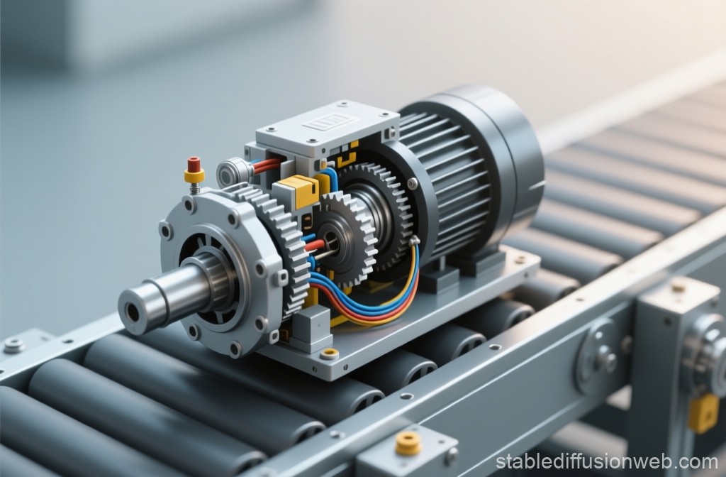 To make the Compact Drive Unit more tangible, let’s consider a real-world application: a conveyor drive in an industrial production line. This scenario allows us to define precise parameters, such as torque, speed, and power requirements, while keeping the system modular and scalable for different use cases.
In this setup, the drive unit must handle continuous operation with a 30-second takt time, support three-shift production, and ensure seamless integration with inline functional testing stations. It also needs to accommodate data exchange for quality control, such as a DataMatrix or QR code on each part for traceability.
The same approach could be applied to other applications — for instance, a compact actuator for regulating industrial valves or dampers, like the project featured in the Grundfos Challenge on GrabCAD. This demonstrates the versatility of the drive unit concept and shows how the methodology can be reused across different systems while defining clear technical parameters.
1. Operational Scenario – From Concept to Context
The Compact Drive Unit is used to power a conveyor segment that moves parts between assembly stations.
The system runs continuously in a three-shift production line, where high uptime and repeatable motion are critical.
Each drive must deliver reliable torque under varying loads, while maintaining precise speed control and providing feedback data to the higher-level control system.
2. Technical Specification (Preliminary)
Mechanical & Performance
Nominal torque: 12–20 Nm
Output speed: 30–90 rpm
Maximum acceleration: 150 rpm/s
Duty cycle: continuous (S1 operation)
Mechanical envelope: 150 × 150 × 250 mm
Mass: < 5 kg
Electrical & Communication
Supply voltage: 48 V DC
Power consumption: up to 250 W
Communication interface: CANopen / Modbus (treated as black box)
Integrated sensors:
Incremental encoder (position feedback)
Torque estimation via current sensing
Dual temperature sensors (motor winding and gearbox housing)
Vibration monitoring (MEMS-based for imbalance and wear detection)
Hall reference sensor for position indexing
(All sensor signals are made available through the control interface.
Signal processing and diagnostic logic remain outside the SE scope and will later be represented as black-box functions or states within the DBSE framework.)
Environmental Conditions
Operating temperature: 0–45 °C
Humidity: up to 90% non-condensing
Protection rating: IP54
Vibration resistance: per IEC 60068
3. Production & Economic Constraints
Because the unit is designed for mass production, the assembly process must meet tight cycle times and repeatable quality metrics. Key assumptions include:
Target assembly cycle: 30 seconds per unit
Shift model: two shifts per day, 8 hours each
Production schedule: 48 weeks per year (approx. 4 weeks maintenance and holidays)
Expected annual production: ~460,000 units
Packaging interface: Eurobox (400 × 300 mm)
Traceability: DataMatrix code engraved or printed on each unit
These constraints directly influence how we will later design the assembly line, the test logic, and even the physical workstation layout. The defined takt time and shift model form the economic foundation of the line concept — every automation level, testing strategy, and logistics step will be derived from these parameters.
4. Verification and Test Interfaces
During assembly, several parameters must be verified to ensure functional integrity before packaging:
Torque output under defined load
Power consumption and thermal behavior
Encoder signal verification
DataMatrix readability and trace link validation
Integrating these checks inline allows for automatic verification without removing the product from the assembly flow — a key principle of connected engineering systems.
5. Why This Step Matters
By grounding our Compact Drive Unit in a specific scenario, we turn abstract requirements into measurable parameters. This step transforms a general product idea into an engineering-ready specification that connects design, production, and verification.
In the next post, we’ll formalize these specifications into document-based requirements for the Initial Phase — setting up the structure for traceability, change management, and system validation within DBSE.
“Beyond Silos” is about more than MBSE.
It’s about rethinking how engineering teams connect —
and making that connection visible.